US Patent: 3,196,752
|
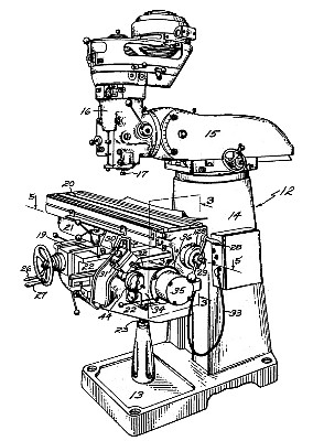
| Transmission Converting Reverse Drive to Variable Speed
|
|
Patentees:
|
| Magnus Wahlstrom (exact or similar names) - Easton, Fairfield County, CT |
| William M. Hoddinott (exact or similar names) - Milford, New Haven County, CT |
|
|
Patent Dates:
|
| Applied: |
Jan. 25, 1962 |
| Granted: |
Jul. 27, 1965 |
|
Patent Pictures:
[
1 | 2 | 3 | 4 | 5 | 6
]
|
|
|
USPTO (New site tip)
Google Patents
Report data errors or omissions to steward
Joel Havens
|
|
Description: |
| Abstract:
A speed up of work table feed is desired for advancing the work more rapidly while it is passing from one cutting operation to another than while feeding the work to the cutting action of the tool. Such situation is encountered for instance when cutting is to be performed on only spaced apart portions of a long workpiece or an separate workpieces spaced apart along the work table. It has been proposed to thus increase the speed of table feed by declutching the table feed screw from a relatively low speed drive and re-clutching it to a relatively high speed drive. This requires tiresome manipulation of clutches which wear rapidly in service and gives rise to special problems of lubrication resulting in undesirably high cost of operation and upkeep. It also has been proposed in a variable speed gear transmission to speed up the rotation of an output shaft in a continuous direction by reversing the direction of running of an input shaft that may be powered at constant speed by an electric motor or other form of prime mover. But transmissions heretofore proposed for this purpose have involved planetary or other gearing arrangements which require that the turning of one or more of the gears be stopped forcibly by applying a brake to cause the shift from low speed drive to high speed drive of the output shaft. The use of brakes possesses similar disadvantages of wear and slippage inherent in frictional devices that are required at one time to arrest and at another time to release moving gears of a power transmitting train. It is an object of this invention so to associate a train of high speed transmission gears with a train of low speed transmission gears that no unclutching or forceful braking action need be exerted on any power transmitting member of the trains of gears and for freeing either train from the inertia of the unlike speed of the previously running other train. Another object is to incorporate such trains of transmission gears together with a constant speed reversible motor or other prime mover reversible as to direction of rotation by which both gear trains are powered in a unitary mechanism applicable to the feed screw that causes traverse of the work carrying table of a machine tool, especially a milling machine. Another object is to leave the usual feed screw turning handle free for manual operation when a motor powered transmission incorporating the present improvements is applied thereto. Another object is to interpose between the slow speed gear train and the table feeding screw or whatever load is to be driven a system of shiftable speed change gears which may be set individually by manual selection to drive the feed screw at differing low speeds while permitting any of such low speeds to be converted to a super high speed for causing rapid traverse of the work table by merely reversing the direction of the motor or other prime mover by which the transmission is powered.
Claim:
A gearing system for transmitting motion from a constant speed rotatively reversible input shaft to a rotatively unidirectional output shaft at different speeds in a constant direction, comprising in combination with said shafts, a main train of permanently meshed speed reduction gears powered at its high speed end by said input shaft and connected to impel said output shaft to run at relatively low speed, an auxiliary train of permanently meshed speed step-up gears powered at its low speed end by said input shaft and connected to impel said output shaft to run at relatively high speed, whereby both of said trains are impelled simultaneously during both slow speed and high speed running of said output shaft, and one-way clutches cooperative respectively with each of said trains, at least one of said clutches being operative to disenable the drive of one of said trains by the other of said trains. |
|

)
)
)
)
)
)