US Patent: 1,935,555
|
| Engraving Machine Cutter
|
|
Patentee:
|
|
| George Gorton (exact or similar names) - Racine, Racine County, WI |
|
|
Patent Dates:
|
| Applied: |
Mar. 05, 1931 |
| Granted: |
Nov. 14, 1933 |
|
Patent Pictures:
[
1 | 2 | 3
]
|
|
|
USPTO (New site tip)
Google Patents
Report data errors or omissions to steward
Joel Havens
"Vintage Machinery" entry for George Gorton Machine Co.
|
|
Description: |
| Abstract:
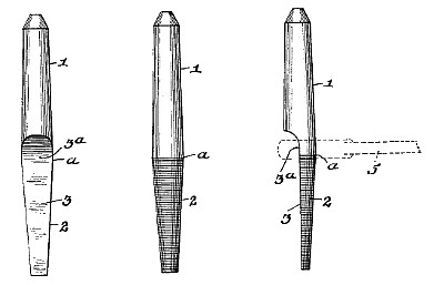
An object of the invention is to improve rotary cutters of the single lip type for so-called engraving machines, die sinking machines, and the like, employed for engraving or cutting designs, indicia, letters, etc. in or on stamps, molds, dies, etc. as distinguished from the ordinary milling machine cutters which must comply with different conditions and requirements- than engraving machine cutters, with the ends in view of reducing the cost, of production, and of producing an engraving machine cutter to overcome certain defects in the engraving machine cutters now in general use, and of increased strength and durability, with a cutting or working end of increased length, "and capable of being more easily applied and removed. A further object of the invention is to produce a single lip rotary cutter for engraving machines, of improved shape and form, to overcome certain disadvantages and difficulties incidental to the form and construction of the engraving machine cutters now in common use, and to avoid the necessity of employing the objectionable pairs of opposite wrench faces on the exteriors of the central portions above the bases of the cutting ends of such old cutters. With the foregoing and other objects in View, my invention consists of a rotary cutter for engraving machines, of new and improved form and structure as more fully and particularly described and specified hereinafter.- Referring to the accompanying drawing, forming part hereof: Fig. 1 shows a form of my improved cutter in side elevation on an enlarged scale, looking at the flat of the cutting -end of the cutter.
Claim:
An engraving machine rotary cutter consisting of a conical shank of uninterrupted longitudinal taper from its base of maximum exterior diameter, and a single lip cutting end projecting longitudinally directly from said base, said cutter having a longitudinal fiat side throughout 125 the length of said cutting end and extended longitudinally of said tapered shank a substantial distance into and along said shank, said extended portion of said fiat side providing the wrench face of the cutter, whereby said cutter no0 is adapted to receive a complementary wrench to operatively fit said wrench face and the base portion of said shank and longitudinally and rotatively force said tapered shank into and from the engraving machine cutter spindle socket. |
|

)
)
)