US Patent: 2,432,943
|
| Boring Mill and Mechanism to Oppose Sag in the Tool Bars Thereof
|
|
Patentee:
|
|
| Ralph M. Shaw, Jr. (exact or similar names) - Edgewater Park, Burlington County, NJ |
| Manufacturer: |
| Not known to have been produced |
|
|
Patent Dates:
|
| Applied: |
Jul. 08, 1943 |
| Granted: |
Dec. 16, 1947 |
|
Patent Pictures:
[
1 | 2 | 3 | 4 | 5
]
|
|
|
USPTO (New site tip)
Google Patents
Report data errors or omissions to steward
Joel Havens
"Vintage Machinery" entry for Pedrick Tool & Machine Co.
|
|
Description: |
| Abstract:
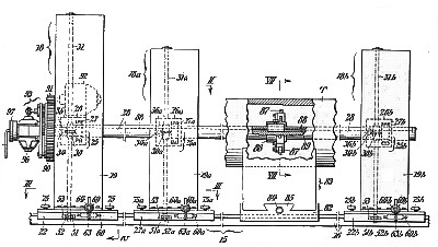
With mills of the two-column types ordinarily used heretofore for boring operations, difficulty was had in keeping the bore true, particularly in machining relatively long objects such for example as gun barrels, due to the sagging of the bar or shaft along which the cutter head travels between the columns during the boring. Thus in these old forms of boring mills the span between the columns and hence the length of the tubes which could be cut was limited by the degree of permissible sag of the tool shaft, the maximum length of allowable span for a 6 inch tool bar for example in existing mills being approximately 12 feet. To eliminate or minimize sag, various expedients have been heretofore resorted to, such as employing tubular bars or shafts instead of bars or shafts of solid cross section to reduce weight; solidly anchoring the ends of the bars or shafts; providing tiedowns in the form of drawing mechanisms in the plane of the bearings for the bar or shaft; or to have followers move along with the cutting tools in snug engagement with the previously cut portions of the bores to hold the bars centered. The first two mentioned of these prior art schemes could not be relied upon for accuracy, and the last mentioned was objectionable because of the difficulty in disposing of the metal trimmings carried along by the followers without attendant scratching or scoring of the machined surface.
Claim:
In a boring mill, a pair of spaced columns; means for horizontally supporting a tube which is to be bored in the interval between said columns; a tool shaft supported axially, within the tube by bearings on said columns with, one end projecting beyond one of the columns; a third column with a vertically-movable bearing in which the projecting end of the shaft is engaged; and means for moving the bearing in said third column to variantly flex the projecting end of the shaft and so compensate for sagging of that portion of the shaft within the tube as the tool is advanced there along. |
|

)
)
)
)
)