US Patent: 2,101,682
|
| Relief Valve
|
|
Patentee:
|
|
| Erling Klafstad (exact or similar names) - Melrose, Middlesex County, MA |
| Manufacturer: |
| Not known to have been produced |
|
|
Patent Dates:
|
| Applied: |
Nov. 04, 1935 |
| Granted: |
Dec. 07, 1937 |
|
Patent Pictures:
[
1 | 2
]
|
|
|
USPTO (New site tip)
Google Patents
Report data errors or omissions to steward
Joel Havens
"Vintage Machinery" entry for Crosby Steam Gage & Valve Co.
|
|
Description: |
| Abstract:
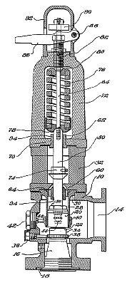
Valves of this character have been heretofore constructed with a cooperating valve disk and seat, the disk being guided in its movements by a surrounding shroud or guiding sleeve and being held against the seat by a loading spring. In this type of construction the valve spindle extends upwardly through the spring, and the thrust- is transmitted to the valve through the spindle. As the size of the valve is increased together with the length of the spindle and spring, serious problems have been encountered due to the fact that the spindle under the influence of the loading spring may tend to exert go a side thrust upon the valve and not only cause -excessive wear but to actually cramp the disk in such a manner that It will stick in either open or closed position. I have discovered that this inherent objection which may become accentuated with the use of large valves at high pressures can be overcome by virtually constructing a spindle section which is sufficiently massive to avoid 'buckling, and which is accurately guided at separated points to compel movement of the spindle in an accurate and predetermined path aligned with the path of movement of the valve disk. Any tendency on the part of the loading spring, if it exists, to exert a side thrust on the spindle is satisfactorily resisted by the guides through which the spindle operates. The spindle itself, however, merely transmits the loading thrust to the" valve disk without any accompanying side or lateral thrust, and relieves the disk and its guide sleeve from undue wear or sticking. Actually the alignment of. the spindle in this manner tends to aid in maintaining accurate movements of the disk and relieves the surrounding guide sleeve of the major portion of its guiding function. In actual practice I propose to connect the spindle to the valve disk in such a manner as to permit rotational movements of the disk, but to restrain the disk against angular movements relative to the spindle. Furthermore, I ,apply the spring load to the remote end of this spindle section at a point not far removed from the outboard guide so that any tendency on the part of the spring to exert a side thrust is resisted adjacent the region- of application. I may connect with the spindle section an extension passing outwardly lengthwise of the spring and serving as a manual connection to raise the spindle and valve from its seat when desired. This extension, however, as will be obvious from the construction, exerts no tendency on the part of the spindle to cramp It In the guide, nor can such a tendency if exerted be communicated to the disk itself.
Claim:
A relief valve comprising a housing, a valve disk, a cooperating seat, a tubular guide member surrounding and closely guiding the disk to compel straight line movement of the disk in a direction normal to the seat, a valve spindle sufficiently massive to avoid buckling under loading strain, a thrust bearing between the end of the spindle and the disk to permit rotative movement of the disk with respect to the spindle, a restraining member connected with the disk and spindle to prevents relative angular movements of the disk and spindle, spindle guides positioned adjacent opposite ends of the spindle to compel accurate movements of the spindle in a path aligned with that 'of the valve disk, and a loading spring engaging with the end of the spindle remote from the disk and beyond the outer spindle guide to impart a loading thrust thereto without affecting the predetermined path of movement of the spindle and connected valve disk. |
|

)
)