US Patent: 663,518
|
| Mechanism for Propelling and Guiding Track Engaging Carriages
|
|
Patentee:
|
|
| Reinhard Scheidler (exact or similar names) - Newark, Licking County, OH |
|
|
Patent Dates:
|
| Applied: |
Mar. 29, 1900 |
| Granted: |
Dec. 11, 1900 |
|
Patent Pictures:
[
1 | 2
]
|
|
|
USPTO (New site tip)
Google Patents
Report data errors or omissions to steward
Joel Havens
"Vintage Machinery" entry for Scheidler Machine Works
|
|
Description: |
| Abstract:
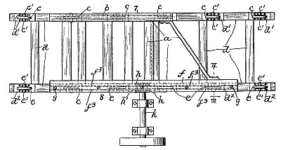
My invention relates to improvements in mechanism for propelling and guiding carriages or vehicles used in carrying logs or in other objects that are to be operated upon by a saw or other tool or machine and the invention pertains more especially to a carriage that is mounted upon and propellable along a straight track and to improved mechanism for propelling the carriage along the track and for positively preventing the slightest displacement of the carriage laterally of the track during the propulsion of the carriage and during the sawing or other operation upon the log or other object borne by the carriage.
Claim:
The combination of the two parallel series of rollers or wheels, the body portion or framework of the carriage propellably mounted upon the said rollers or wheels and comprising a timber arranged above and longitudinally of one of the said series of rollers or wheels, a metallic bar arranged at and longitudinally of the under side of the said timber and provided, upon its upper side, centrally between itsside or longitudinal edgs, with a 'reinforcing rib or flange,' extending into and longitudinally of the aforesaid timber, which bar is provided, upon its under side, with two depending parallel flanges extending longitudinally of the bar, and the last mentioned rollers or wheels extending between the said flanges. |
|

)
)