US Patent: 275,279
|
| Traction-Engine
|
|
Patentees:
|
| Abraham O. Frick (exact or similar names) - Waynesboro, Franklin County, PA |
| William H. Snyder (exact or similar names) - Waynesboro, Franklin County, PA |
| Manufacturer: |
|
Frick Co. - Waynesboro, Franklin County, PA |
|
|
Patent Dates:
|
| Applied: |
Jan. 25, 1883 |
| Granted: |
Apr. 03, 1883 |
USPTO (New site tip)
Google Patents
Report data errors or omissions to steward
Joel Havens
Vintage Machinery entry for Frick Co.
|
|
Description: |
| Abstract:
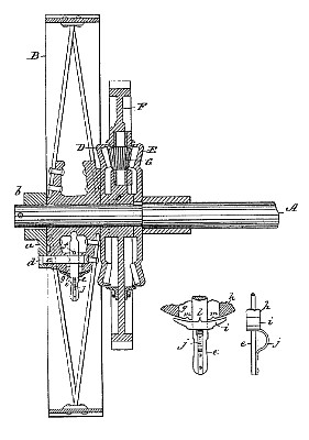
In traction-engines it is desirable to have the two main-wheels driven independently, so that the inner wheel in turning a curve maybe stationary, or nearly so, while the outer wheel is rounding the larger curve, and for this purpose it is customary to employ a compensating-gear consisting of two bevel-wheels on the axle, facing each other, one of which is connected to one of the main wheels, and the other of which is connected to the axle which is rigid with the other main wheel, and between which bevel-wheels is arranged a loose gearwheel receiving motion from the engine and bearing bevel-pinions which mesh with the bevel-wheels on each side of the same. With this construction of compensating-gear it sometimes happens that one main wheel will get in a mud- 3~5 hole or upon a sandy or soft foundation while the other wheel is on hard ground. In such case the wheel that is on hard ground will become stationary, and the wheel which is on soft ground will spin around at high velocity, all the power of the engine being lost in the movement of this wheel. The object of our invention is to prevent this contingency; and to this end it consists in a peculiar construction of device whereby the loose wheel is rigidly locked to the axle, so that in such case the power of the engine cannot become diverted to one wheel, but both wheels are rotated together, and the wheel which is on hard ground is made effective for drawing the engine out.
Claim:
he combination of~ the axle A, having arm a, the loose wheel B, having bolt c and lever e, and the compensating mechanism D E F G. |
|