US Patent: 42,903
|
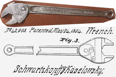
| Wrench
|
|
Patentees:
|
| Louis Robert Victor Schwarzkopff (exact or similar names) - Berlin, Kingdom of Prussia |
| E. Kaselowsky (exact or similar names) - Berlin, Kingdom of Prussia |
|
|
Patent Dates:
|
| Granted: |
May 24, 1864 |
|
Patent Pictures:
[
1 | 2
]
|
|
PATENT L. SCHWARTZKOPFF BERLIN - with edited drawing from Patent 42,903 |
USPTO (New site tip)
Google Patents
Report data errors or omissions to steward
Stan Schulz
|
|
Description: |
| The patent is for a self-adjusting mechanism using a linking bar, an eccentric on the end of a pivoting handle, and a sliding jaw. The specifications note the jaw faces could be smooth for nuts or have gripping teeth for pipe. This is the first U.S. wrench patent from a European patentee. The Inventor's full name was obtained (and regularized) from Ron Geesin's account of British manufacture (THE ADJUSTABLE SPANNER, vol. 2, pg. 47). Kaselowsky likely was the German patent attorney / agent.
Corresponding British patent GB-186300945 was registered April 21, 1863. Schwarzkopf produced the single opening version in Berlin.
Schwarzkopf's Adjusting Spanner (the name appears with one or two "Fs") was produced in Britain by the Argus Works (Robert Crookes) of Sheffield. A modification to allow locking the adjustment was proposed in British patent GB-188502260 registered Feb. 19, 1885.
Schwarzkopff's self-adjusting wrench patents (this design in both single- and- double opening styles, and an earlier version with teeth on one jaw and matching teeth on a swinging handle) were noted in German language trade and technical journals in the early 1860s.
1864 items in DINGLER'S POLYTECHNISCHES JOURNAL describe "SCHWARZKOPFF'S Universal-Schraubenschlussel (minus the illustrations) and list 3 sizes. An item in an 1864 issue of "Journal fur Gasbeleuchtung.." notes Schwarzkopff's 4-year Bavarian patent for the "internal gear adjust" Universal-Schraubenschlussel was issued Aug. 27, 1862.
A known example marked " PATENT L. SCHWARZKOPFF BERLIN" may reflect this "internal link" version. It has the "loop end" handle shown in this patent, rather than the "knob end" handle shown in representations of the earlier patent. |
|

)
)