US Patent: 87,908
|
| Improvement in sawing-machine
|
|
Patentee:
|
|
| John Casson (exact or similar names) - Sheffield, England |
|
|
Patent Dates:
|
| Granted: |
Mar. 16, 1869 |
|
Patent Pictures:
[
1 | 2
]
|
|
|
USPTO (New site tip)
Google Patents
Report data errors or omissions to steward
Jeff Joslin
Vintage Machinery entry for John McDowall & Sons
Vintage Machinery entry for Oliver & Co., Ltd.
|
|
Description: |
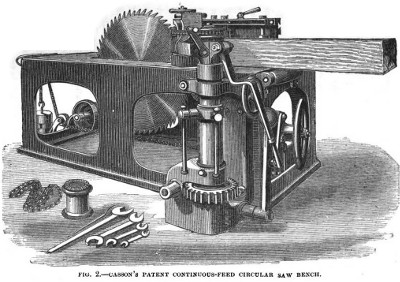
| The innovations are a stock-feeding mechanism and a means of adjusting the tabletop for cutting-depth.From M. Powis Bale's "Woodworking Machinery, Its Rise, Progress and Construction": "Fig. 2 represents a circular saw bench with a self-acting continuous feed, patented by Mr. John Casson, of Sheffield, in 1868 (makers, J. M. McDowall and Sons, Johnstone, near Glasgow). The wood is fed to the saw continuously, without stopping or reversing the machinery, by means of a single continuously revolving grooved roller, of slightly conical form, between which roller and the fence the wood to be sawn is placed. The roller is affixed to an axis which turns in bearings carried by a horizontal arm, formed in two parts, one of which slides telescopically within the other, so that the arm can be extended when a small saw, or contracted when a large saw, is used. The adjustment of the said arm is effected by means of a nut-and-screw arrangement, which admits of the axial motion in its socket of that part of the arm which carries the feed roller, so that the roller can be set in an oblique position for bevel-sawing. The said socket is formed on a vertical tubular shaft, which turns in a bearing fixed to the frame of the bench, and passes through another tubular shaft furnished with a weighted arm. A set screw passing through the outer shaft engages in a longitudinal slot or groove formed in the inner shaft, so that the latter can slide but cannot turn in the former."By this arrangement the arm carrying the feed roller can be raised or lowered. The weighted arm referred to carries a toothed quadrant, which receives motion from a worm on a shaft, which is turned as required by a hand wheel, and can be thrown in and out of gear by means of a rocking standard and weighted lever. When the wood to be sawn is placed between the fence and the feed roller, the worm and quadrant are thrown into gear, and the hand wheel is turned till the feed roller is brought to the requisite distance from the fence. The wood is then introduced, and the quadrant and worm being thrown out of gear, the weight comes into action, and the feed roller is pressed against the wood. The roller is driven by a strap or chain passing over pulleys, one of which is fixed on the axis of the said roller, the other being keyed to the upper end of a shaft, which passes through the inner tubular shaft before referred to, and also through a worm wheel, to which the said central shaft is connected by means of a groove-and-feather arrangement. The worm wheel is driven by a worm in a shaft, which receives motion by means of band pulleys from the saw spindle. The feed roller can be removed when cross-cutting, &c, has to be done."We have seen the above self-acting feed in motion for cutting deals, &c, and ordinary light work, and it answered its purpose well. The inventor claims that this feed may be advantageously applied to band saws and deal frames, but we have never seen the same in operation." |
|

)
)