US Patent: 968,884
|
| Indicating Surface Gage
|
|
Patentees:
|
| William H. Reisner (exact or similar names) - Hagerstown, Washington County, MD |
| Victor E. Middlekauff (exact or similar names) - Hagerstown, Washington County, MD |
|
|
Patent Dates:
|
| Applied: |
Mar. 31, 1909 |
| Granted: |
Aug. 30, 1910 |
|
Patent Pictures:
[
1 | 2 | 3 | 4 | 5 | 6 | 7 | 8 | 9
]
|
|
|
USPTO (New site tip)
Google Patents
Report data errors or omissions to steward
Joel Havens
"Vintage Machinery" entry for L. S. Starrett Co.
Wikipedia entry for the L. S. Starrett Company
History of the L. S. Starrett Co.
|
|
Description: |
| Pervice, Goldsborough & Neil, patent attorneys
Abstract:
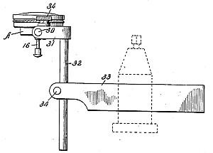
This invention relates to indicating surface gages and more particularly to gages of this type such as described in Letters Patent, No. 773,983, granted to William H. Reisner, on November 1st, 1904. One of the objects of this invention is to simplify greatly the interior mechanism of the gage shown and described in the patent referred to. It is aimed to reduce the number of operative parts of the mechanism to a minimum and also to provide a construction in which the geared connection between the grooved,. barrel and, the pointer-carrying arbor is dispensed with, as such a connection makes the instrument more or less inaccurate due to the play between the gears and the impossibility of cutting their teeth with the requisite exactness and accuracy. According to this invention, the grooved barrel is located centrally in the case or cup of the gage and carries the pointer directly, the actuating pushpin being arranged eccentrically, instead of concentrically, with respect to the case. A further object of the invention is to provide improved means for mounting the gage so that it may be readily mounted in the tool-post of a lathe, or in a similar place, in such a manner as to be adjustable in a number of ways with respect to the work.
(6) The invention also purposes the provision of an improved attachment adapted for use with -the gage to indicate when a bore or other cavity formred-in.the work is of greater or'-less diameter at its inner portion than at its notith or off' center with respect to the center of the lathe, or other machine in which 'the work is held., A still farther object of the inven~tion is to provide 'an iiproved attachment by wvhich' the gage may be clamped on a metal cutting tool, such as used in a lathe; shaper, or planer, and properly adjusted with respect to the work.
Claim:
In a surface gage, the combination of a case, a bridge extending across the case, a push pin guided vertically in the bridge, a second bridge above the first, and a pointer-carrying barrel journaled in the second bridge and rotated by said push pin. |
|

)
)
)
)
)
)
)
)
)