US Patent: 857,207
|
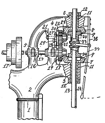
| Stop Mechanism for Drill Presses
|
|
Patentee:
|
|
| Sherman C. Schauer (exact or similar names) - Cincinnati, OH |
|
|
Patent Dates:
|
| Applied: |
Feb. 18, 1907 |
| Granted: |
Jun. 18, 1907 |
USPTO (New site tip)
Google Patents
Report data errors or omissions to steward
Joel Havens
"Vintage Machinery" entry for Cincinnati Machine Tool Co.
|
|
Description: |
| Abstract:
My invention relates to speed-changing devices of the class adapted to use on drill presses, other machine-tools, or elsewhere; and the objects of my improvement are to mount the device in an adjustable position in relation to its driving-gears, whereby it is most accessible to the operator in changing the longitudinal movement of a spindle to different predetermined ratios from its constant rotative speed; to drive said device by gearing from the spindle that its action may be positive and accurate; to provide a plural number of means to discontinue the longitudinal movement of the spindle during its rotative movement, and in construction to especially adapt said device to best serve the purpose for which it is intended.
Claims:
1. In combination, a rotative spindle, an adjustable head, a speed-changing device mounted thereon, gear mechanism arranged to transmit rotary motion thereto from the spindle, rack-and-pinion mechanism arranged to move the spindle longitudinally, and gear mechanism arranged to transmit motion thereto from said device.
2. The combination of two rotative shafts, respective series of idle gears thereon, a clutch mechanism arranged to turn either gear of one series with its shaft, a rack-and-pinion mechanism, a key movable thereby to turn either gear of the other series with its shaft, and a cone of gears arranged to turn in unison one gear thereof meshing only with a corresponding idle gear in one series another gear thereof meshing only with a corresponding idle gear of the other series, and one gear thereof meshing with a corresponding idle gear in each series.
3. The combination of two shafts journaled in fixed bearings, a series of different-sized gears mounted idly on each shaft, an eccentric pin, a clutch mechanism actuated thereby to turn with one shaft either gear thereon, a rack-and-pinion mechanism, a key actuated thereby to turn with the other shaft either gear thereon an intermediate shaft, different-sized gears thereon arranged to turn in unison and to mesh with corresponding gears in either of the said series.
4. The combination of two rotative shafts, a series of idle gears on each, an eccentric-pin, a clutch mechanism actuated thereby to turn either of one series of gears with its shaft, a rack-and-pinion mechanism, a key actuated thereby to turn either of the other series of gears with its shaft, an intermediate shaft, a series of gears thereon arranged to turn in unison and to mesh with corresponding gears in either of said series of idle gears.
5. The combination of two shafts journaled in fixed bearings, a series of idle gears on each shaft, an eccentric-pin, clutch mechanism actuated thereby to turn either gear of one series with its shaft, a rack-and-pinion mechanism, a key actuated thereby to turn either gear of the other series with its shaft, and means independent of either shaft arranged to transmit the motion to either gear of one series from either gear of the other series.
6. The combination of a rotative spindle, a gear mounted at a fixed point, a shaft splined there in gear mechanism arranged to transmit motion to said gear from the spindle, a speed changing device adjustable in relation to said gear and actuated by said shaft, rack-and-pinion mechanism arranged to move the spindle longitudinally, and means arranged to transmit motion thereto from said device.
|
|