US Patent: 842,989
|
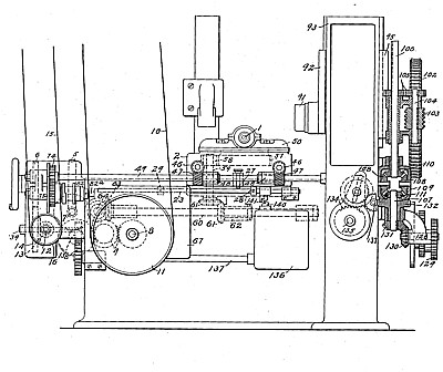
| Spiral Cutting Machine
|
|
Patentee:
|
|
| Richard T. Wingo (exact or similar names) - Providence, RI |
| Manufacturer: |
| Not known to have been produced |
|
|
Patent Dates:
|
| Applied: |
Jan. 16, 1904 |
| Granted: |
Feb. 05, 1907 |
USPTO (New site tip)
Google Patents
Report data errors or omissions to steward
Joel Havens
"Vintage Machinery" entry for Brown & Sharpe Mfg. Co.
|
|
Description: |
| WilMarth H. Thurston - patent attorney
The invention relates more especially to machines for cutting spirals in which the work is carried by a rotary blank support and is acted upon by a rotary cutter, the axis of which is at an angle to the axis of the blank-support and in which either the cutter or the blank is reciprocated parallel to the axis of the blank. In such machines the cutter should be out of cutting relation during the return movement of the reciprocating support, and this may be provided for by moving either the cutter or the work. It has heretofore been customary to throw the blank and cutter out of cutting relation by a swinging movement of either the cutter or blank support. The clearing movement with such construction is in the arc of a circle with a constant liability that the cutter may contact with the wall of the cut as the blank and cutter are thrown out of cutting relation, and the danger of such action increases as the angle between the axes of the blank and cutter increases. This objectionable feature in the prior constructions is eliminated by certain features of the present invention winch provide for a relative movement between the cutter and blank at right angles to the axes of the blank and cutter in clearing the cutter from the blank, that is to say, if the axes of the blank and cutter are arranged horizontally, as is customary, the blank and cutter are thrown out of cutting relation by a direct vertical movement either of the blank or cutter, and thus all danger of injury to the work by the cutter in clearing the work is eliminated. It is preferred to move the cutter at right angles to the axes of the blank and cutter in throwing the blank and cutter out of cutting relation rather than to move the blank, and certain further features of invention relate to the construction and arrangement which provides for such movements of the cutter. In this class of machines the blank and cutter should be in cutting relation whenever the movement of the reciprocating support is forward or in the direction of the cutting movement and should be out of cutting relation whenever the movement of such support is, in the direction of the return or non-cutting movement. To insure this, the mechanism for throwing the blank and cutter into and out of cutting relation is so controlled by the device for alternately connecting the reciprocating support with the feed mechanism and the return mechanism that the operation of such device in connecting either mechanism with the -support to reverse its previous movement results in the operation of the mechanism for throwing the blank and cutter into and out of cutting relation. Another feature of invention relates to the means for operating the mechanism for throwing the blank and cutter but of cutting relation which insures the proper timing of such mechanism under all conditions. This mechanism is driven by a clutch which is intermittently thrown into and out of operation by the cooperation of rotary and non-rotary members, the rotary member or members, as the case may be, being carried by the clutch and the non-rotary member or members being movable into and out of the path of the rotary member or members and the members being so arranged and operated that in disengaging a non-rotary member from a rotary member to throw the clutch into operation a non rotary member is moved into the path of a rotary member. Thus the operation of the devices for throwing the clutch into operation sets devices for throwing it out, so that there is no-danger of failure to throw out at the proper time or of operating improperly. Further features of invention relate to the construction of the mechanism for throwing the blank and cutter out of cutting relation and locking it in position between operations
|
|