US Patent: 79,381
|
| Tool Rest for Engine Lathe
|
|
Patentee:
|
|
| Cyrus Newhall (exact or similar names) - Hinsdale, Cheshire County, NH |
| Manufacturer: |
| Not known to have been produced |
|
|
Patent Dates:
|
| Granted: |
Jun. 30, 1868 |
USPTO (New site tip)
Google Patents
Report data errors or omissions to steward
Joel Havens
|
|
Description: |
| Baldwin & son - patent attorneys
The objects of my improvement are to easily adjust the cutting-tool of an engine-lathe to the work to be done, and also to compensate for the wear of the working parts of the tool-rest; to which ends the improvements herein claimed consist First, in a novel method of mounting the cutting-tool of an engine-lathe in a tool-post supported in a rocking-block hinged to the slide-plate by a pivot arranged centrally beneath the block, parallel to the axis of the lathe, and directly beneath the tool-post, substantially as hereinafter set forth.
Second, in a novel method of combining, with a tool-support, rocking on a hinge parallel with the axis of rotation of the lathe, and in the same vertical plane as the tool-post, a device for adjusting and holding the point of the tool in any position desired.
Third, in a novel method of combining, with a rocking-tool support, a device for tightening the joints of the hinge on which the tool-post rocks, to compensate for its wear.
Fourth, in a novel method of compensating for the wear of the joints of the. device by which the cutting tools adjusted and held in position.
Fifth, in a novel method of constructing the sockets of the adjusting-screw.
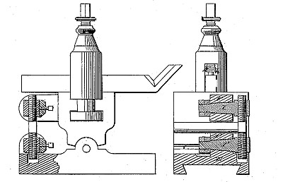
In turning iron and other metals in an engine-lathe, the working joints are necessarily subjected to a heavy strain, which causes them to wear unequally. In my efforts to compensate for this wear, I found it necessary to remodel the tool-rest usually employed. To carry out the objects- of my invention, I construct the tool-rest in three pieces
First, a sliding plate, having the usual motions on the lathe-bed;
second, a block, rocking on a long hinge or bearing parallel to the axis of the lathe;
third, a tool-post, sliding and turning freely in the usual way in a slot in the rocking block. The wear of the hinge of the rocking-block is compensated by tightening the eye-bolts which connect the block with its pivot. The angle of the tool-post is adjusted by a right-and-left screw, one end of which enters a socket on the slide-plate, and the other a corresponding socket on the rocking-block. The wear of this screw in its sockets is taken up by wedges, forming a part of the sockets in which the screws work, which wedges are tightened by pinch-screws in the sockets. These sockets are mounted on the ends of tapering spindles, passing through tapering holes in brackets on the slide-plate and rocking-block, and the wear on these spindles is compensated by nuts, screwing on their ends. By this, means the tool is held rigidly up to its work, and that wobbling of the tool, so fatal to accurate work, prevented.
|
|