|
Description: |
| Abstract:
In that now well-known type of steam fire-engines, in which the steam-cylinders and pump-cylinders are vertical, and in which one piston-rod serves, by elongation, for one pump and one steam-cylinder, it is desirable to produce such an arrangement of means as will convert the engine into a self-propeller without the addition of extra steam-cylinders for the propulsion of the engine, considered as a vehicle, over the road.
Claim:
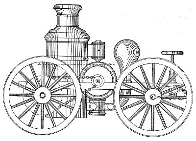
The steam-cylinders a are shown as vertical, and as working direct upon the pumps b, giving rotation to a cranked shaft, c, by means of yokes, in which work l1ocks, which are fitted to the cranks in a manner common and well known to engine-makers. From this rotating crankshaft one or more of the wheels of the engine, considered as a vehicle are rotated to propel the vehicle over the road. On the shaft c are fitted sprocket-wheels d, and on the wheels e, of the vehicle, are fitted sprocket-wheels f, and the endless chains g pass over each pair of sprocket-wheels d and f, so that it will 'be seen that when the pistons of the cylinders a reciprocate, rotation of the wheels e must result, and the said wheels will act as drivers. The sprocket-wheels d are so fixed upon the shaft c as to be easily loosened thereon, so that shaft c can rotate in the hubs of said sprocket-wheels without rotating them, as is necessary for the engine-to stand still and throw water. In the drawings, the sprocket- wheels d are shown as arranged to be clamped, by turning up the nuts h, on the shaft c, which clamp the inner faces of said sprockets against the outer faces of the flanges a; which are made fast on shaft c; or, instead of holding the sprockets dl, so that they will, by friction alone, rotate with shaft e, keys, through said sprockets and 'shaft, may be used, with or without the nuts h and flanges 4, and then, to let the. shaft rotate freely without rotating the sprocket, d the keys must be removed when it is desired to have the vehicle stationary. I prefer to have the wheels a loose, or so as to rotate upon a fixed axle, rather than fixed upon a rotating axle, as, with the sprocket-wheels f, fixed to wheels rotating on a fixed axle, corners and curves can be turned by the vehicle with facility. But in the arrangement which I have stated that I prefer, if both wheels a are rotated, where two steam-cylinders are employed, the shaft a should be divided, so as to allow a difference in the piston-velocity of each cylinder, to permit the required difference. of rotation of the driving-wheels needed in turning angles or corners, and to prevent slip of the drivers, and consequent strain of the parts. Indeed, where the shaft c is continuous, whether rotated from one or two steam-cylinders, I prefer to drive the vehicle with but one driving-wheel loose upon a fixed angle, keeping the vehicle to its course by means of the steering-wheels. |
|

)
)
)