US Patent: 63,928
|
| Turning Lathe
|
|
Patentee:
|
|
| H. L. Morse (exact or similar names) - New Bedford, Bristol County, MA |
| USPTO Classifications: |
| 82/15 |
| Assignees: |
|
S. A. Morse - New Bedford, Bristol County, MA |
| Manufacturer: |
| Not known to have been produced |
|
|
Patent Dates:
|
| Granted: |
Apr. 16, 1867 |
|
Patent Pictures:
[
1 | 2
]
|
|
|
USPTO (New site tip)
Google Patents
Report data errors or omissions to steward
Joel Havens
|
|
Description: |
| Munn & Co.-patent attorneys
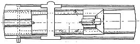
This metal-working lathe was assigned to Stephen A. Morse, inventor of the twist drill (patent 38,119) and founder of the Morse Twist Drill and Machine Co. At roughly the time this patent was granted, Mr. Morse was working on what became known as the Morse standard taper shank. Since the purpose of this lathe design is to improve its ability to turn tapers, perhaps this lathe was used in the manufacture of tapered shank drill bits.
The object of this invention is to construct a lathe on which straight work may be turned as well as tapering, and the latter as good as the former. In the lathe now generally in use, straight work could be well done; but for doing tapering work the foot-stock was adjusted laterally. This would have worked very well if the centre pins would not thereby have been brought out of their relative positions. The head-stock remaining stationary, its centre pointed in the old direction, that is, in line with the longitudinal centre line of the lathe, while the centre of the foot-stock, having been brought out of the centre line of the lathe, pointed towards the centre of the head-stock. It was, consequently, perfectly impossible to neatly secure the material to such a lathe for tapering work. Another defect of the old lathes consisted in the omission of a proper gauge for adjusting the tool to the work. There was, generally, an adjustable rest provided, but that could not be made use of with sufficient accuracy, as the tool was being worn out and had to be resharpened. The difference thus occasioned in the length of the tool made a really exact readjustment of the rest impossible, unless there was a proper gauge, by means of which the original position of the tool could always be ascertained and retained. My invention completely overcomes all these difficulties. It consists, first, in securing to the top of the lathe a plate which cannot be moved either length or sideways, but which turns on an imaginary centre in the middle portion of the lathe. The head-stock is rigidly secured to this plate. The foot-stock slides on it longitudinally. The plate is turned by means of a crank operating a screw on the head end of the plate. An index at the foot end of the lathe enables a very accurate adjustment of the plate. The carriage, with the tool-rest, slides independently of the movable plate on the lathe itself, and retains its original direction under all circumstances. By turning the upper plate it will be understood that both the stocks being attached to the same, their respective centres will point exactly towards each other. The angle of taper being ascertained by the aid of the index, the work can be very accurately performed. The carriage and rest always remain in a direction, which is at right angles with the longitudinal centre line of the lathe. My invention consists, second, in the attaching a gauge to the foot-stock, whereby the original position of the tool can at once and at all times be ascertained. |
|

)
)