US Patent: 626,933
|
| Apparatus for Drilling Wells
|
|
Patentee:
|
|
| Joseph Reid (exact or similar names) - Oil City, Venango County, PA |
|
|
Patent Dates:
|
| Applied: |
Feb. 16, 1899 |
| Granted: |
Jun. 13, 1899 |
|
Patent Pictures:
[
1 | 2 | 3
]
|
|
|
USPTO (New site tip)
Google Patents
Report data errors or omissions to steward
Joel Havens
"Vintage Machinery" entry for Joseph Reid Gas Engine Co.
|
|
Description: |
| Abstract:
My invention relates to apparatus through the medium of which explosive-engines may be combined with ordinary well-drilling apparatus in a manner to meet all the requirements of the drilling operation and the handling of the tools and performance of other work incident to the operation of deep-well boring. Explosive engines have not been available for this purpose, owing to the impracticability of readily reversing them or accurately varying their speed at will or stopping or starting. My invention provides means whereby explosive-engines may be used as the source of power employed for performing all of the various kinds of work incident to deep-well drilling.
My invention consists in combining with the ordinary well-drilling rig an explosive engine, means whereby the speed of the engine may be controlled at will, means whereby the engine may be connected or disconnected with the well-rig or such connections reversed, and a brake for controlling the operation of the well rig when the driving power is disconnected
Claims:
1. In combination with a well-drilling rig, a constantly running explosive-engine, means whereby said engine may be at will connected, disconnected, or reversed in its connections with the drilling rig, a speed controlling valve for regulating the admission of explosive material to the engine, whereby the speed of the engine may be regulated at will, a manually-controlled and positively-actuated lever and rod connection for controlling said valve extending to the derrick-floor, and means for controlling the connecting and reversing mechanism, also extending to points where they are simultaneously within reach of the operator; substantially as set forth.
2. The combination of a drilling-rig shaft having independent pulleys and a brake wheel, a clutch-shaft having loose pulleys and a clutch for connecting either of said pulleys with the shaft, reverse connections between the clutch-shaft pulleys and the pulleys on the drilling-rig shaft, an explosive-engine provided with a speed-regulating valve, and having driving connection with the clutch-shaft, and controlling-levers connected respectively to the brake and the reversing clutch and to the speed-regulating valve; substantially as and for the purposes set forth. I
3. In combination with the shaft of a well drilling rig, pulleys upon said shaft for driving it in opposite directions, a clutch-shaft having loose pulleys with reversed connections to the rig-shaft pulleys, an explosive-engine which is provided with governor-valves, and is connected to the clutch-shaft, a lever substituted for the governor and connected with the governor-valve stem, and suitable controlling-levers within the reach of the operator respectively connected with the reversing-clutch and with the governor-valve lever; substantially in the manner and for the purposes set forth.
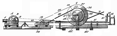
4. The combination of the drilling-rig shaft 36 having the pulleys 27 and 29, and the brake wheel 40 provided with the brake-band, the shaft 23 having independent pulleys 24, 25 loosely mounted thereon and respectively connected by straight belt 26 and cross-belt 28 with the pulleys 27 and 29 on shaft 36, a constantly running explosive engine connected with the shaft 23, clutches whereby either of the pulleys 24, 25 may be made to rotate with the shaft 23, or both left loose thereon, and means substantially as described whereby the brake-band and the clutches are under control of the operator; substantially as explained.
5. In combination with a well-drilling rig, the reversely-connected independent pulleys for driving said rig in opposite directions, having operating connections, rods 15 and 14 controlling said valves, the fulcrumed lever 16 to which said rods are connected and controlling connections comprising suitable levers within the reach of the operator, and connections between the respective levers and the governor-valve lever and the reversing clutch; substantially as and for the purposes set forth.
|
|

)
)
)