US Patent: 61,166
|
| Tool Rest for Lathes
|
|
Patentees:
|
| T. J. Currier (exact or similar names) - Worcester, Worcester County, MA |
| A. M. Black (exact or similar names) - Worcester, Worcester County, MA |
| Manufacturer: |
| Not known to have been produced |
|
|
Patent Dates:
|
| Granted: |
Jan. 15, 1867 |
USPTO (New site tip)
Google Patents
Report data errors or omissions to steward
Joel Havens
|
|
Description: |
| Thomas H. Dodge, patent attorney
Abstract:
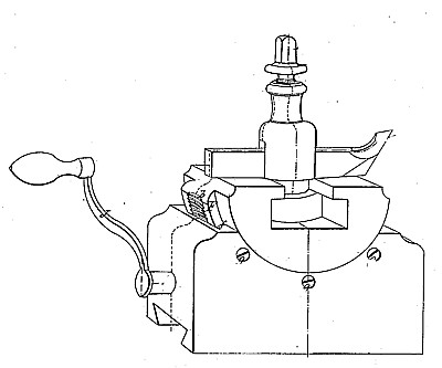
In the drawings, A represents what is generally termed the poppet-block, which fits and works upon the slide-rest of the lathe in the ordinary manner, B represents the tool-post; C the tool; D the tool-rest, and E the set-screw by which the tool is held in place. The usual mode of elevating or lowering the point a of the tool C is to loosen the screw B and place something under either the front or rear end of the tool, the rest part D not being made adjustable for that purpose in machines heretofore made. There is a great objection to this mode of adjusting the tool, since in the operation the tool is very liable to slip either forward, back, or laterally. We obviate all these objections by making the part D, upon which the tool C rests, in circular and dove-tailed form to fit a groove of corresponding shape in the part A, as fully shown in the drawings. Upon the outer surface of the dove-tailed part F of the part D is cut a section of a screw-thread, b, into which the screw G works, the latter being placed upon the end of a spindle or shaft, H, winch is arranged to operate as fully shown in the drawings. The screw G is first slipped up into the slot c in the part D, when the shaft or spindle H is run in through the screw, the latter having a groove, to receive the spline or stay-pin e on shaft G. J is a handle or crank by which shaft H is turned. By turning shaft H screw G will cause the part D to move to elevate or depress the point of cutter C, depending upon the direction in which the shaft is moved. In fig. 3 the point of the cutter is shown in red lines turned up to illustrate the operation of our invention. To keep the part D from having any lateral play a metal packing, f, is placed in one of the dove-tailed grooves and forced against the part F by screws g g g. The end of shaft H may be made to receive a pipe wrench if the crank or handle is found objectionable. It will be seen that by our invention the point of the tool can be adjusted up or down with great precision, while screw G will always hold it in position, when once adjusted, until the position of the parts is changed again by the movement of the shaft H. The invention is applicable to any machine where there is a necessity for elevating or lowering the point of the tool creaser, polisher, or other similar devices. |
|