US Patent: 56,339
|
| Screw Threading Machine
|
|
Patentee:
|
|
| Joseph Tangye (exact or similar names) - Birmingham, West Midlands County, England |
| Manufacturer: |
| Not known to have been produced |
|
|
Patent Dates:
|
| Granted: |
Jul. 10, 1866 |
USPTO (New site tip)
Google Patents
Report data errors or omissions to steward
Joel Havens
|
|
Description: |
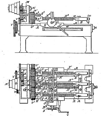
| This invention relates to a peculiar arrangement and combination of machinery or apparatus for cutting screws, whereby a considerable saving in time is effected, inasmuch as I am enabled to cut two, three, or more screws simultaneously. In carrying out my said invention in practice I construct a lathe-bed similar to an ordinary screw-cutting lathe-bed, but of a sufficient width to accommodate two or more screw-blanks side by side, upon which screw-threads are to be cut in lieu of being only wide enough to receive a single screw-blank, as heretofore. The several screw-blanks are carried between two sets of corresponding centers, one set being arranged and constructed in the ordinary manner and made adjustable in order to admit of the blanks being inserted and removed, while the other set is fitted in a head-stock secured to the driving end of the lathe-bed. This head-stock extends the full width of the bed, and carries on its outer face a fixed axis or stud-center, upon which revolves freely a cone of driving-pulleys, to which is secured so as to rotate with them a spur-pinion in gear with a spur-wheel on a short shaft working in a bushed bearing in the head-stock. On the inner end of this short shaft there is keyed a spur-pinion, which is in gear with and drives simultaneously two spur-pinions, respectively, carried by two of the fixed centers in the headstock, and round which they rotate freely. The third center, (when three are used,) or that next to the front of the lathe, carries a spur pinion corresponding to the pinions on the other two centers, and deriving its motion from the other two by a carrier-pinion working loose on a stud-center in the head-stock. It will thus be seen that on rotating the driving-pulleys the whole of the pinions on the centers in the head-stock will be rotated simultaneously and in the same direction. The rotatory motion of the pinions above referred to is imparted to the three screw-blanks to be cut into screws by means of a projecting pin from the face of each pinion coming in contact with a radial pin secured to the head of each of the blanks, and hence as the pinions revolve they will carry round with them their respective screw-blanks. The slide-rest which carries the cutting-tools is provided with as many holders as there are tools required, each holder being provided with its own tool adjusting or setting screw. The traverse motion is imparted to the slide rest in the usual manner from a leading-screw working in a split nut on the slide-rest and driven by any convenient or well-known arrangement or combination of change-wheels, according to the pitch of the screw-thread to be produced. The depth of cut of the several tools is regulated by a single feeding-screw carried by the slide-rest, as in single screw-cutting lathes, with this difference, that it operates upon two, three, or more tool-holders simultaneously. |
|