US Patent: 5,622,092
|
| System For Simultaneously Setting Stroke On A Crankshaft Lathe
|
|
Patentee:
|
|
| William R. Gleason (exact or similar names) - Los Osos, San Luis Obispo County, CA |
| Manufacturer: |
| Not known to have been produced |
|
|
Patent Dates:
|
| Applied: |
Mar. 20, 1995 |
| Granted: |
Apr. 22, 1997 |
USPTO (New site tip)
Google Patents
Report data errors or omissions to steward
Joel Havens
|
|
Description: |
| This application is a Continuation-in-Part of application U.S. Ser. No. 08/294,104, filed Aug. 22, 1994, now U.S. Pat. No. 5,408,906, issued Apr. 25, 1995. The term of this patent shall not extend beyond the experation date of patent #5,408,906.
Numerous improvements have been made to lathes used in machining crankshafts; see U.S. Pat. Nos. 3,789,709; 3,896,690; 4,261,234; 4,305,689; 4,779,495; and 4,895,057. However, none of the lathes disclosed in the foregoing patents are the type commonly used for rebuilding crankshafts of all types and sizes. A common problem exists for all such lathes during the rebuilding of crankshafts used for internal combustion engines and compressors. Because the crank journals or crankpins are offset from the main longitudinal axis of the crankshaft, the crankshaft must be positioned in the lathe so that the crankshaft moves in a circular rotary path. Consequently, the crankshaft must be readjusted and reclamped for each new offset or stroke position of the crankshaft. Each reclamping position requires time-consuming steps before the crankshaft is ready for machining.
Abstract:
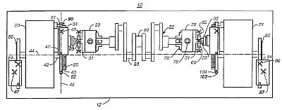
A system is disclosed for simultaneously and more efficiently setting the stroke position of a crankshaft on a crankshaft lathe and a method of using the system in combination with the lathe for regrinding, building-up by welding or other machining of journals of the crankshaft. The system includes slide blocks and slides in operable combination with rack and pinion gears means for simultaneously positioning the crankshaft from a zero loading position to an offset position transverse to the longitudinal axis of the lathe.
Claim:
In a crankshaft lathe having a headstock, a tailstock and a holding chuck, headstock holding chuck back plate, tailstock chuck back plate, and a main spindle shaft operably connected to each of said headstock and said tailstock, a system for simultaneously setting the stroke position of a crankshaft comprising:
(a) headstock mini-shaft, said mini-shaft having a first end operably connected to the headstock holding chuck back plate and a second end;(b) headstock rack and pinion gear means mounted on the second end of said headstock mini-shaft; (c) tailstock mini-shaft, said minishaft having a first end operably connected to the tailstock holding chuck back plate and a second end; (d) tailstock rack and pinion gear means mounted on the second end of said tailstock mini-shaft;
said headstock and tailstock rack and pinion means for simultaneously positioning the crankshaft from a zero loading position in which the main spindle shaft for the headstock and tailstock are in alignment with the crankshaft along the longitudinal axis of the crankshaft lathe to an offset position transverse to the longitudinal axis. |
|