US Patent: 499,159
|
| Driving Mechanism for Lathes
|
|
Patentee:
|
|
| Francis H. Crafts (exact or similar names) - Buffalo, Erie County, NY |
|
|
Patent Dates:
|
| Applied: |
Sep. 21, 1892 |
| Granted: |
Jun. 06, 1893 |
|
Patent Pictures:
[
1 | 2
]
|
|
|
USPTO (New site tip)
Google Patents
Report data errors or omissions to steward
Joel Havens
"Vintage Machinery" entry for F. H. Crafts
|
|
Description: |
| Charles J. Good - patent attorney
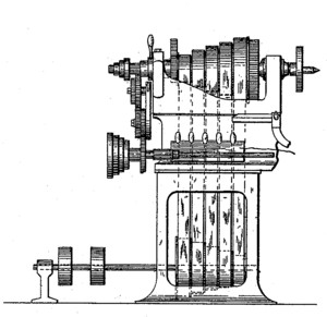
Even though this patent was for a Driving Mechanism for Lathes, it was incorporated into a Radial Arm Drill ( see image #2).
The Crafts Radial Drill.
The most important feature of this drill, which is built by F. H. Crafts of Buffalo N. Y., is to be found in the method employed to obtain the several changes of speed required in machines of this type. The changes from the fastest to the slowest speed can be made instantly, and any tension of the belt can be secured to carry the lightest or heaviest load. This is accomplished by the employment of four endless belts, each of which is provided with a tightener. These tighteners are controlled by a series of levers, having notches planed in them at intervals of 1/2 inch. This enables the operator to make rapid changes and to almost double the capacity of the drill. The general arrangement of the belts is shown at the left in the engraving. The drill is made unusually heavy in all its parts. It has power raising and lowering attachment, the drill spindle has quick return, is counter-weighted and provided with automatic feed. Either a box or tilting table is provided. All the shafts, spindles, worms and worm rings are made of steel, and all gearing is cut from the solid and the main gearing is made of steel. The principal dimensions of the No. 1 machine are : Diameter of column, 10 inches; distance from floor to highest point of column, 7 1/4 feet; distance from elevating screw to center of drill spindle when at the extreme point of the arm, 3 feet 7 inches; vertical range of arm on the column, 2 1/2 feet; receives under spindle over base, 4 feet 2 inches receives under spindle over floor, 4 feet 9 1/2 inches; traverse of spindle, 15 inches; floor space occupied, 4 feet 7 inches by 7 feet 4 inches; weight, 4500 pounds.
from Iron Age magazine
13 Jul, 1893
Patented in Canada, #CA-46,598. |
|

)
)