US Patent: 47,997
|
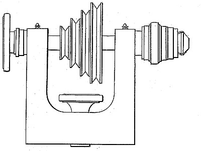
| Turning Lathe
|
|
Patentee:
|
|
| John Stark (exact or similar names) - Waltham, Middlesex County, MA |
|
|
Patent Dates:
|
| Granted: |
May 30, 1865 |
USPTO (New site tip)
Google Patents
Report data errors or omissions to steward
Steve Gosselin
"Vintage Machinery" entry for Stark Tool Co.
|
|
Description: |
| R. H. Eddy - patent attorney
My improved lathe has a tubular arbor and certain devices applied thereto for enabling a rod to be extended into and through the arbor longitudinally thereof, and to be duly centered and clamped in place therein, and with its axis coincident with that of the arbor. However, the rod may vary in diameter within certain limits to which the clamps may be adapted. My I invention is intended to overcome a difficulty incident to the said patented lathe, in which the clamps were not only expansive in transverse directions, but while being clamped on a piece of wire were movable in a longitudinal direction, that is to say, they were retracted within the arbor by means of a screw and a hand-wheel or nut screwed thereon. This longitudinal movement of the clamps will occasion a corresponding or nearly corresponding longitudinal movement of the rod while being clamped within the arbor. The smaller the rod may be in diameter the greater will the longitudinal movement of it be likely to be. At any rate, it will be more or less irregular or uncertain. Often when articles of given length are to be turned by a tool held by a slide-rest working at right angles with the axis of the arbor, this longitudinal movement of the clamp becomes very inconvenient, for on account of variation in the diameter of the wire the operation of clamping the wire will cause it to be drawn more or less longitudinally out of place, or away from the gage against which its end may be placed. Thus for turning pillars and screws for watches, and for fine work in general, where there is to be equality of dimensions in pieces of one kind, the patented lathe is objectionable or cannot be used with proper advantage and certainty. In carrying out my invention, the clamp though expansible transversely, is stationary in longitudinal directions relatively to the arbor,, and is contracted by means of a movable socketed annulus sliding in or on the arbor, and moved by means of a screw and a nut, the whole being substantially as hereinafter described, and as exhibited in the accompanying drawings. |
|