US Patent: 404,057
|
| Micrometer Caliper
|
|
Patentee:
|
|
| Morris F. Smith (exact or similar names) - New Haven, CT |
|
|
Patent Dates:
|
| Applied: |
Jan. 17, 1889 |
| Granted: |
May 28, 1889 |
|
Patent Pictures:
[
1 | 2 | 3
]
|
|
|
USPTO (New site tip)
Google Patents
Report data errors or omissions to steward
Joel Havens
L. S. Starrett Co.-125th Anniversary
"Vintage Machinery" entry for L. S. Starrett Co.
|
|
Description: |
| This 6 inch Micrometer was #128 in the Starrett catalog.
This is a 0-1" micrometer mounted on a bar with a pin and a set of precision bushings. Of the 6 possible positions in the example shown (image #2), only one was .001" off. The rest were less than that.
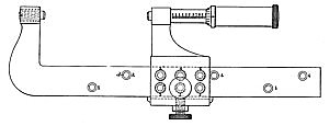
My invention relates to that class of micrometer-calipers, which measures distances greater than one inch by means of moving a slide, which carries one of the caliper-points. The objects of my invention are accurate and expeditious adjustment of the slide and improved means for taking up the wear of the micrometer-screw. To enable others to make and use my improved calipers, I will give a description of the same in detail, reference being had to the drawings hereto annexed. The beam A, Fig. 1, has the two parts a and &. The part a is rectangular and of equal size throughout its length and the part 5 integral with the part a is bent at a right angle to it and terminates in the cylindrical enlargement c, which is tapped to receive the screw B. The part a is perforated in two lines parallel and near to the sides of the beam, into which hardened-steel bushings d are forced. These bushed holes are arranged to operate in conjunction with the bushed holes in the slide, so that when bushings having like numbers are brought in line the micrometer-screw being in the position shown in Fig. 1, the distance between caliper points C and D will be as many inches or units of measure as the number on the coincident bushings indicates. Thus in Fig. 1 bushings 3 are in line, and the distance between points C and D is three units. Fractional measurements are obtained in the same manner as in the ordinary micrometers. The screw B is reduced in size where it protrudes from the beam, and is chamfered at the end C, and forms one of the caliper-points. The slide E is a rectangular box fitted to the beam, except on the lower side, where room enough is left for the shoe or gib g to fill. On its lower side a circular boss is raised, which is tapped to receive the thumb-screw which passes through the lower side of the slide and comes against the shoe g. The shoe g is turned up at each end at right angles to hold it in place when the screw is released. On the upper side of the slide extends upward, the arm e, terminating in the cylindrical enlargement , which is tapped to receive the part F. When the slide is in place on the beam A, the axes of the threaded parts c and are in line. The wider sides, h, of the slide are perforated in two parallel lines, which are in the same planes as the lines of the holes in the beam, and the holes are equal in number. Into these holes, bushings i are forced, and are ground out, as is hereinafter explained. The pin G-, with the knurled head, is fitted to these bushings and holds the slide from endwise movement when the tool is in use. |
|

)
)
)