|
Description: |
| R. F. Osgood, patent attorney
My improvement relates to key seating or slotting machines, and is designed to do the work in a simpler and more effective manner than in ordinary machines for the purpose.
Having thus described my invention, I claim:
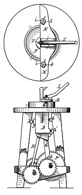
1. In a key seating or slotting machine, the combination of the fixed cotter F, the sliding head E, the adjusting-screws h h', the stiff bar G, attached to the sliding head, and the pivoted box jj provided with a socket which receives the lower end of the bar, as shown and described, and for the purpose specified.
2. In a key seating or slotting machine, the. combination of the fixed cutter F, the sliding head E, the adjusting-screws h h', the stiff bar G, the pivoted box J, the pitman H, crank wheel I, and eccentric gears M M, as shown and described, and for the purpose specified.
3. In a key seating or slotting machine, the combination, with the sliding head E, guide bar G, and pivoted box J, of the adjusting screw, resting in a bearing, ff, and serving to gage the movement of the sliding head in cutting the slot, and the lever L, for pressing the cutter forward to its work, as herein shown and described.
4. In a key seating or slotting machine, the combination, with the sliding head E, guide bar G, and pivoted box J, of the gage-screws hh', as shown and described and for the purpose specified.
5. In a key seating or slotting machine, the combination, with the cotter P, of the lever L, pivoted to the cross-bar K, said lever being provided with a thin edge, which extends down back of the cutter, the whole arranged as described, so that the operator, bearing upon the lever, can exert pressure upon the cutter, as, herein set forth. |
|