GB Patent: GB-190,717,289
|
| An Improved Mode or System of Producing Rolling Motions, applicable to Wheel Gear Cutting, and like, Machines, Requiring Circumferential Work of an Inter-related Character
|
|
Patentee:
|
|
| Robert Arthur Bruce (exact or similar names) - Leeds, England |
| Manufacturer: |
| Not known to have been produced |
|
|
Patent Dates:
|
| Applied: |
Jul. 29, 1907 |
| Granted: |
Apr. 23, 1908 |
|
Patent Pictures:
[
1 | 2
]
|
|
|
Espacenet patent
Report data errors or omissions to steward
Joel Havens
"Vintage Machinery" entry for Joshua Buckton & Co.
Robert Arthur Bruce
|
|
Description: |
| Note: Early English patents (pre 1916) were numbered by the year and started at patent #1 at the start of each year in January. The patent # used in DATAMP represents the year of issue of the application and the patent #. This patent is #17,289 of the year 1907.
Abstract:
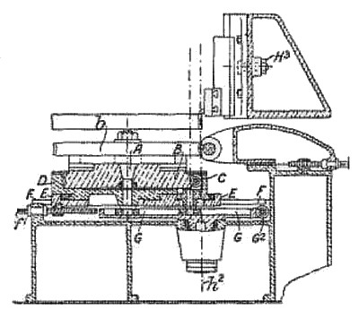
A system of link-work is applied to produce a true rolling motion between a cylindrical and a plane surface, and the system is stated to be applicable for making or treating toothed gearing by milling, or shaping, or by grinding with reciprocating or revolving tools, and for embossing and for printing upon cylindrical or plane surfaces. In one arrangement, members D, E, F, Fig. 2, form a compound slide, and the member D carries an arbor A which supports a master wheel B and a blank b, and a slide C<3> carrying a worm, screw, or rack C. In the case of a worm or screw, a dividing- apparatus may be attached. A link G is centred on a pin C<4> carried by the slide C<3> with its axis in the plane of rolling of the master wheel, and is slotted to receive a block A<1> on the arbor A and a block on a pin H carried by the member F. The axis on the pin H is in a plane tangential to the blank b. If the slide C<3> is the fixed or anchored portion of the linkage, motion of the slide D in the direction of the arrow will produce a true rolling of the blank b with respect to the plane pp- In a modification the fixture may be the slide D, and in a further modification the pin H. In another arrangement, the slide C<3> moves on ways which are not parallel to the ways connecting the slides D, E, and the link G is replaced by a system of three links. Fig. 3 is an example of the mechanism as applied to cutting worm-wheels. The blank b, master wheel B, and arbor A are carried by the slides D, E, and the slide E is adjustable on the slide F by a screw f<1>, this adjustment being the only one necessary to set the machine for different blank diameters by bringing the central pitch circle into position over the fixed pin h<2>. The link G is shown fitted with worm gearing G' for oscillating the system. When arranged for cutting spur-wheels, the fly-cutter saddle is replaced by the slotting - saddle H<3>, Fig. 3A. More than one cutter may be used, and the apparatus' may be arranged for continuous working, in which case the worm C is given a continuous rotary movement in relation to the cutter speed in known manner. If cutting-tools are mounted on an arm on the arbor A, racks may be cut. |
|

)
)