GB Patent: GB-190,627,029
|
| An Improved Mode and Apparatus for the Self-registration of the Stresses and Strains of a Specimen in a Testing Machine
|
|
Patentee:
|
|
| Joseph Hartley Wicksteed (exact or similar names) - Leeds, England |
| Manufacturer: |
| Not known to have been produced |
|
|
Patent Dates:
|
| Applied: |
Nov. 28, 1906 |
| Granted: |
Jul. 18, 1907 |
Espacenet patent
Report data errors or omissions to steward
Joel Havens
Joseph Hartley Wicksteed
"Vintage Machinery" entry for Joshua Buckton & Co.
|
|
Description: |
| Note: Early English patents (pre 1916) were numbered by the year and started at patent #1 at the start of each year in January. The patent # used in DATAMP represents the year of issue of the application and the patent #. This patent is #27,029 of the year 1906.
Abstract:
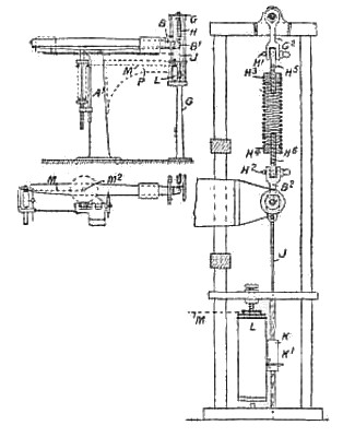
Testing strength of materials.- Relates to means for obtaining a diagram on a testing-machine of the steelyard type free from the effects of inertia due to the travelling poise. The steelyard arm is over-weighted and balanced by a spring, so that throughout the test the steelyard is in equilibrium. The longer arm B, Fig. 1, has the knife-edge B<1> supported by a spring H fitted on two cylindrical ends H<3>, H<4>, Fig. 5, in which are centrally screwed eyebolts H<5>, H<6>, which allow adjustment and ensure true axial working of the spring. A connection J from the lower attaching-shackle B<2> supports a carrier K for the pencil K<1>, the diagram drum L being driven by a flexible connection M arranged, as shown in Fig. 1, for a tension test. The eye-bolts H<5>, H<6> are irremovably attached by means of pins H', H<2> to shackles B<2>, G<2> as shown. An arm P, shown in dotted lines in Fig. 1, prevents variation in the length of the connection M due to play between the standards A<1>, G. The balancing-spring and diagram device may be at opposite ends of the machine, or both may be arranged at the end of the short arm ; or the balancing-spring may have a flexible connexion adapted to rotate the diagram drum, the pencil being travelled by the connection M. Fig. 7 shows the application of the device to a torsion test, the flexible connection M being wrapped round the cylindrical mounting M<2> of the specimen, or round the specimen itself if circular. For obtaining a " polar" diagram, the chart is carried on the axis of the specimen, and a longitudinally-moving rod carrying the pencil has a light returning-spring and is operated by a flexible connection to the end of the steelyard. Reducing - gear may be employed for altering the scale of the diagram. |
|