|
Description: |
| NX series patents are pre-July 1836 patents that do not have numbers and are not listed in the X patent series. They have been arbitrarily assigned NX numbers, which consists of the issue date in ISO format followed by a single number to separate multiple patents issued on the same date. This is to allow them to be entered into the Datamp file. They are entered here for reference and further research only.
“The usual method, now practiced, of forming the roll of yarn on a shuttle bobbin, is, to begin at the head of the bobbin, and fill it to its full diameter, and then proceed onward towards the point of the bobbin, keeping the point of the yarn all the way in a conical shape; this is done by short vibrations of the bobbin-rail, or lifter, (so called, together with one other slow and regular motion moving the bobbin downward, as it fills with yarn. And when the bobbins are filled to the point, or, in other words, when the bobbin-rail has fallen to its lowest position, the machinery then requires to be placed back again as it originally was, at the commencement of filling the bobbin; consequently all the bobbins require shifting at one time, whether they are full or not; and, in altering the size of the yarn, require an alteration in said regular motion. But, in the improvement, no alteration is necessary, either in the commencement of filling the bobbin, or in the different sizes of the yarn, as the vibrating, or traverse, motion, which spreads the yarn over the bobbins, always traverses the whole length of them, varying only at the point of the bobbin, at which place the traverse motions reach, or extend, one beyond another, for six or more vibrations in succession, and then returning, alternately forming a conical point to the spire of the yarn. This motion and manner of filling a bobbin, is nearly the same as that used in the common throsel or spinning frame, (excepting that the bobbins are filled moderately, tapering, and with the above described variations.). There are various ways to produce the above described variations in the traverse motion—the following is one selected from a number, as being the most handy and convenient, and requiring but little alteration from the common throsel, or spinning frame-that is, to substitute a cam-wheel (in the place of the common heart) of sufficient size to contain on its surface, six or more cams, projecting from the wheel, and acting on the same lever, or levers, which said heart acted on. These cams are similar in shape to the point of a common heart, and are of different lengths, each one projecting further from the wheel, or its centre, than the former, carrying the vibrating, or bobbin-rail, further, or lower down, at one time than at another, forming a conical point to the spire, or roll of yarn, as above described. It is necessary that the point of the yarn should be formed by the points of the cams, so that a quicker motion may be gained, which is necessary in forming such point.
The above described manner of forming the spire, or roll of yarn, on a weaver's, or shuttle bobbin, and the application of the above improvement to the filling frame and throsel, I claim as my invention, desiring an exclusive property therein, and in the application of said invention and improvements to all and any spinning frame, or frames, that are, or may be, constructed for the purpose of spinning on a weaver's, or shuttle bobbin, &c.
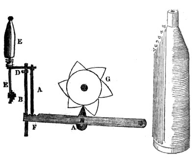
Description of the Figures. Fig. 1. Represents a sketch of the lever and appendages of a common heart motion (so called) used in the common spinning frames, for the purpose of elevating, and giving to the bobbin the proper traverse, or vibrating, motions; also of a cam wheel, which is substituted for the common heart, for the express purpose of varying the length of the traverse, or vibrating motions at the point of the bobbin, so that a conical form should be given to the point, or spire, of yarn at that place.
The cams, or projections, of said wheel vary in length; one projecting further than another, from the surface, or centre, of said wheel, producing the above-mentioned variations, forming a conical point to the roll of yarn.
Said wheel is confined to the same shaft to which said heart belonged.
ÅA, Is the lever and its appendages, which is acted upon by a weight, or spring, bearing it up to said wheel, or cams.
B, The end of the spindle rail.
D, End of bobbin, or vibrating rail, on which the bobbin and whorl sets.
EE, The spindle and can.
F. The sliding bar, to which the bobbin is confined, serving to steady it.
G, The cam wheel.
Fig. 2. Represents a bobbin filled with yarn, and by tracing the vertical line from the head of the bobbin to A, thence back again to the head, and from that to B, and back again, and so on, will show how the traverse motion conducts and distributes the yarn over the bobbin, and how the conical point is formed.”
Journal of the Franklin Institute Vol. 5, Aug. 1829 pgs. 126-127
|
|