|
Description: |
| NX series patents are pre-July 1836 patents that do not have numbers and are not listed in the X patent series. They have been arbitrarily assigned NX numbers, which consists of the issue date in ISO format followed by a single number to separate multiple patents issued on the same date. This is to allow them to be entered into the Datamp file. They are entered here for reference and further research only.
“This improvement consists of a cup, or can, placed on the top of a dead, or still, spindle, around the surface of which the yarn revolves, being drawn by the bobbin as it twists and receives it. This cup, or can, answers the purpose of the common flyer, in keeping the yarn at a proper distance from the bobbin, and in guiding and distributing it thereon. The bobbin may be either a weaver's bobbin, or a common spinning bobbin, at the option of the manufacturer, and turns on the spindle, receiving its motion from a whorl, which also turns on the spindle, and with which it is connected at its base, by two pins, or studs, extending upward from the whorl, and entering two corresponding holes, or mortises, in the base of the bobbin, the whorl being banded gives positive motion to the bobbin. The bobbin rail is similar to the one in common use, excepting that it is made to steady the spindles by having the holes through which the spindles pass, of the same size as the spindles. It vibrates like the bobbin rail in common machines, and on it the whorl is set, obeying the motion of the rail, moving the bobbin up and down on the spindle, and spreading the yarn over the whole length of the bobbin, the lower edge of the cup, or can, being the guide. The rail to which the spindles are confined, or what may be called the spindle-rail, is a plate of cast-iron. In this rail are scores, which exactly fit the spindles, and by which, with the assistance of an eye, or clasp-bolt, they are kept perfectly steady; and by these bolts the spindles can easily be adjusted and raised or lowered so that the lower edge of the cup, or can, which is the guide of the yarn, may suit the filling of the bobbin. The cup, or can, rests and is hung upon a shoulder at the top of the spindle, and its cavity is sufficiently large to admit the bobbín. This can be lifted off and put on again with ease. It must be taken off to change the bobbins, and to mend or piece the yarn when the bobbin is in the can. In finding broken ends, or in piecing the yarn, the bobbin is lifted by the thumb or finger, from the pins, or studs, that connect it with the whorl, and the whorl is allowed to run while the yarn is put in a proper position to be mended; then the thumb, or finger, is withdrawn from the bobbin, and it falls to its proper place, connecting itself again with the whorl. When spindles are placed close to each other, it may be necessary to surround each cup, or can, with a cylindrical, or semi-cylindrical tube, to prevent the yarns from interfering as they pass round their respective cans.
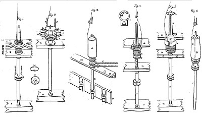
References to Fig. 3, Plate 1.
A, cup, or can.
B, bobbin, which may be either a spinning bobbin or a weaver's bobbin.
C, whorl, on which the bobbin stands, and with which it is connected.
D, spindle.
E, piece of the bobbin, or vibrating, rail.
F, piece of the spindle rail.
G, band (lettered C.)
H, eye, or clasp-bolts, which secure the spindles (not lettered.)
The yarn is seen leading down from the rollers of a common spinning frame.
The can, A, rests on a shoulder at the top of the spindle and can be taken off and put on with ease. Around the surface of this can, the yarn revolves; being drawn by the bobbin, as it twists and receives it. The lower edge of the can is perfectly smooth and serves to guide and distribute the yarn on the bobbin.
The bobbin, B, stands on the whorl, C, and is connected with it by two pins, or studs, that extend upward from the whorl, entering a hole, or mortise, in the base of the bobbin; and the whorl, being banded, causes the bobbin to have a positive motion.
The whorl, C, sets on the bobbin, or vibrating rail, E, and turns on the spindle, moving up and down, obeying the motions of said rail, spreading the yarn over the whole length of the bobbin. The holes in the rail, E, through which the spindles pass, are of the same size with the spindles themselves; by which means they are kept steady.
The rail, F, is a stationary plate of cast-iron, to which the spindles are confined.
The bolts, H, through which the spindles pass, have a screw-nut on the backside of the rail, F, by which the spindles are drawn close to the rail, and held perfectly steady.
When the spindles are placed close to each other, it may be necessary to surround each cup, or can, with a cylindrical, or semicylindrical tube, to prevent the yarns from interfering as they pass round their respective cans.”
Journal of the Franklin Institute Vol. 4 1829 pgs. 62-65
|
|