|
Description: |
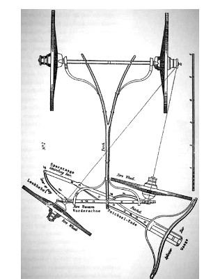
| This invention, which relates to the steering gear for a carriage, is due to George Lenkensperger of Munich but it is now strongly identified with the patentee in Britain, Rudolph Ackermann. Virtually all modern road cars use "Ackermann steering": when the car steers into a curve the inner wheel turns more than the outer wheel. Reportedly, though, Erasmus Darwin (1731-1802) used this trapezoidal steering linkages on his coaches decades earlier. Another person who deserves some credit is Charles Jeantaud (1840-1906) of France, who was perhaps the first to use this type of steering in an automobile, as in French patent FR-318,897."At or near the ends of the fore transome, C, are holes which form the sockets wherein the vertical axles, E, E, are inserted, and they are secured by nuts, &c., in the manner of linch pins in order that the vertical axles E, E, may turn in their sockets and form the centres round which the axle-arms have their horizontal rotary motion for the purpose of placing the fore wheels in an oblique position when the carriage is to be turned. F, F, are levers or stays projecting backward from the elbow or bend where the vertical axles and the axle-arms unite; these stays are connected together by the controlling bar, B, which is united to the extremities of both stays by knuckle-joints, H, H, and there if any motion is given to one vertical axle and axle-arm the other must partake of it. The futchel, A, passes through a bow or crook underneath the fore transome with which it is united by the perch-bolt, S, making the centre of motion for the pole, and the futchel projecting behind the fore transome forms a lever, R, whose centre of motion is at S. The controlling bar is connected with the end, R, of the futchel by a pin. The splinter bar, T, is bolted to the futchel as usual and braised by iron stays; it must be fixed at such a distance from the perch-bolt as to allow full play for the fore wheels at their greatest obliquity. In turning, the futchel moves on the perch-bolt and moves the controlling, bar, H, B, H, end-ways; this communicates motion to both stays, F, F, and consequently to both the axle arms and fore wheels so as to put them into an oblique direction in respect of the hind wheels and then the carriage is prepared for turning. If the distance between two vertical axles, E, E, be made more than the distance between the joins, H, H, at the ends of the controlling bar, B, it will occasion that fore wheel which is on the side to which the carriage is intended to turn to have a greater degree of obliquity than the opposite wheel. This is conducive to quick turning because the axles of all the four wheels of the carriage become direct to one point, O, as shown by dotted lines, but if the length of the controlling bar, B, be made equal to the distance between the two vertical axles, then the fore wheels always stand parallel to each other." |
|