|
Description: |
| J. C. Lennon - patent attorney
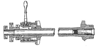
My invention relates to mechanical opening and closing spring chucks, and it has for its object the improvement in the construction of such devices whereby they are simplified and rendered more efficient.
Having described my invention what I claim is:
1. In a device of the character specified, a pair of cooperating rotating members, the one movable lengthwise with reference to the other, fingers pivotally mounted on one member and adapted to bear upon the other to shift the one with reference to the other, and a loose ring encircling and engaging said fingers on the outer sides thereof, with means for shifting the ring to close the fingers, for the purpose specified.
2. In a device of the character specified, a pair of cooperating rotating members, a housing in which said members are mounted, one member movable lengthwise with referenee to the other, fingers pivotally mounted on one member and adapted to bear upon the other, a loose ring embracing said fingers, and a lever to actuate said ring, with a diagonal slot in the housing through which said lever passes whereby the oscillation of the lever will shift the ring to close the fingers.
3. In a device of the character specified, a pair of cooperating rotating members, a housing in which said members are pointed, one member movable lengthwise with reference to the other, fingers pivotally mounted on one member and adapted to bear upon the other, a loose ring embracing said fingers, provided with an external annular groove, an actuating ring seated in said groove and a lever secured to said actuating ring, with a diagonal slot in the housing through which said lever passes whereby the oscillation of the lever will shift the ring to close the fingers.
4. In a device of the character specified, the combination with a housing and a hollow spindle mounted to rotate therein, and a quill mounted in said spindle and movable lengthwise thereof, with a spring chuck., secured to the quill, a tension ring secured to the quill, a plurality of fingers pivotally secured to the spindle and adapted to bear on said tension ring to shift the quill, a loose ring encircling and engaging said fingers on the outer sides thereof, with means for shifting the ring to close the fingers, for the purpose specified.
5. In a device of the character specified, the combination with a housing and a hollow spindle mounted to rotate therein, and a quill mounted in said spindle and movable lengthwise thereof, with a spring chuck secured to the quill, a tension ring adjustably secured to the quill, a plurality of fingers pivotally secured to the spindle and adapted to bear on said tension ring to shift the quill, a loose ring embracing said fingers, and a lever to actuate said ring with a diagonal slot in the housing through which said lever passes whereby the oscillation of the lever will shift the ring, for the purposes specified.
6. In a device of the character specified, the combination with a housing and a hollow spindle mounted therein, and a quill mounted in said spindle and movable lengthwise thereof, with a spring chuck secured to the quill, a tension ring adjustably secured to said quill, a ring secured to said spindle provided with a plurality of longitudinal slots, with fingers pivotally mounted on the ring in said slots, with their outer ends adapted to bear upon the tension ring, a loose ring mounted on said slotted ring to close said fingers, and means for shifting the ring, for the purpose specified.
7. In a device of the character specified, the combination with a housing and a hollow spindle mounted therein, and a quill mounted in said spindle and movable lengthwise thereof, with a spring chuck secured to the quill, a tension ring adjustably secured to said quill, with means for locking the tension ring in place, a ring secured to said spindle provided with a plurality of longitudinal slots, with fingers pivotally mounted on the ring in said slots, with their outer ends adapted to bear upon the tension ring, a loose ring mounted on said slotted ring to close said fingers, and means for shifting the ring, for the purposes specified.
8. In a device of the character specified, the combination with a housing and a hollow spindle mounted therein, and a quill mounted in said spindle and movable lengthwise thereof, with a spring chuck secured to the quill, a tension ring adjustably secured to said quill, a ring secured to said spindle, provided with a plurality of longitudinal slots, with fingers pivotally mounted on the ring in said slots, with their outer ends adapted to bear upon the tension ring, a loose ring mounted on said slotted ring to close said fingers, and a lever to actuate said ring, with a diagonal slot in the housing through which said lever passes whereby the oscillation of the lever will shift the ring, for the purpose specified.
|
|