|
Description: |
| Newell S. Wright - patent attorney
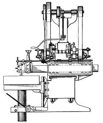
Our invention has for its purpose and design an improved draw cut foundry shaper adapted for various uses, as for example, to remove shrink heads or surplus stock from steel castings or other work for which it is adapted.
What we claim as our invention is:
1. In combination a frame, a reciprocatory ram carried by said frame, means to reciprocate the ram, a tappet bar provided with tappets to control the reciprocation of the ram, a shifting clog actuated by the tappet bar, a crank actuated by the shifting dog, a cam actuated by said crank, a clutch shaft provided with clutches, and means actuated by the cam to shift said clutches.
2. The combination of a frame, a reciprocatory ram projecting laterally from said frame and having a cutter head on its outer end, means for controlling the actuation of said ram, a tappet bar extending outward from the frame parallel with said ram, tappets on said bar, a member movable with the ram to engage said tappets and move the bar, a support on the frame for the bar within which said bar is adapted to be adjusted longitudinally, means for locking said tappet bar in its adjusted position, and means actuated by the movement of the tappet bar for operating the controlling means.
3. The combination of a reciprocatory ram, means for actuating said ram, means for changing the direction of movement of the ram, a movable member for actuating said means, a tappet bar adapted to be actuated by said ram, locking means for adjustably connecting the tappet bar to said member, and means whereby the locking means is adapted to be operated by the turning of said bar.
4. The combination of a reciprocatory ram, means for actuating said ram comprising clutches, means for operating the clutches to change the direction of movement of the ram, a member adapted to be moved to actuate said means, a tappet bar, an arm on said ram engaging and supporting said tappet bar, tappets on said bar adapted to be engaged by said arm, and a locking member on said member through which the tappet bar is longitudinally adjustable for holding said bar in its adjusted position relative to said movable member.
5. The combination of a frame, a reciprocatory ram projecting laterally from the frame and having a cutter head on its outer end, means for actuating said ram comprising clutches, means for operating the clutches, a tappet bar extending outward parallel with said ram, tappets on said bar, a member movable with said ram to engage said tappets a handle on one end of the bar adjacent to the cutter head, a member adjustably supporting the tappet bar, and means operated by the turning of said bar for locking the same in its adjusted position.
6. The combination of a reciprocatory ram, means for actuating said ram, means for changing the direction of movement of the ram, a member adapted to operate the changing means provided with a tapering bore, a tappet rod adjustable longitudinally through said bore, a split bushing for said bore having screw threaded engagement therewith and adapted to be turned by the turning of the rod to force the bushing into the bore and clamp the rod, tappets on said tappet rod, and means on the ram to engage said tappets.
7. The combination of a reciprocatory ram, means for reciprocating said ram comprising clutches, means for operating the clutches, a member for actuating said means provided with an internally screw-threaded and tapered bore, a tappet bar adjustable longitudinally in said bore, tappets on said bar, a member movable with said ram to engage said tappets, and a split bushing externally screw-threaded to engage the bore and adapted to be turned within the bore by turning the tappet bar.
8. The combination of a reciprocatory ram, means for reciprocating said ram comprising clutches, a tappet bar actuated by the ram, a cam bar slidable longitudinally with the tappet bar and provided with means 75 for adjustably holding said bar, a shifting dog actuated by said bar, and means for transmitting motion from said dog to actuate the clutches and change the direction of travel of the ram.
9. The combination of a reciprocatory ram, means for reciprocating said ram, means for changing the direction of travel of said ram, a tappet bar, tappets on said bar, a member movable with said ram to engage said tappets, a cam bar, a block on the cam bar having a tapering and screw threaded bore, a split bushing in said bore connected to said bar to be turned thereby, and a member actuated by the cam bar for actuating the means for changing the direction of travel of the ram.
10. The combination of a frame, a reciprocatory ram on said frame extending laterally therefrom, means for actuating said ram comprising clutches, a tappet bar extending parallel with said ram, an arm on the outer end of the rain engaging and supporting said bar and through which the bar is adapted to slide, tappets on said bar adapted to be engaged by said arm, a bar extending parallel with the tappet bar and slidable therewith, means on said sliding bar for engaging and adjustably holding the tappet bar, and means actuated by the sliding bar for operating the clutches.
11. The combination of a support, a traveling frame upon said support, a hollow shaft, means for transmitting motion from said shaft to move the frame upon its support, no clutches on said shaft, a rod extending through said hollow shaft to simultaneously operate said clutches, means for transmitting, a continuous motion to said shaft through one of said clutches, a reciprocatory ram on the frame, means for actuating said, ram, and means for transmitting an intermittent motion to the other of said clutches from said ram actuating means.
12. The combination of a support, a traveling frame upon said support, a shaft, means for transmitting motion from said shaft to move the frame upon its support, clutches on said shaft, means for simultaneously operating said clutches to throw one into operative position and the other out of operative position, a driving shaft, means for transmitting a continuous motion in either direction from said driving shaft to the first named shaft through one of said clutches, a reciprocatory ram on the frame, means for actuating said ram, a bell crank actuated by said means and carrying a gear segment, a gear engaged by said segment, and means for transmitting motion from said gear to the other of said clutches.
|
|