US Patent: 78,594
|
| Lubricator
|
|
Patentees:
|
| Timothy Holland (exact or similar names) - Cincinnati, Hamilton County, OH |
| John T. Cody (exact or similar names) - Cincinnati, Hamilton County, OH |
| Manufacturer: |
|
J. T. Cody - Cincinnati, Hamilton County, OH |
|
|
Patent Dates:
|
| Granted: |
Jun. 02, 1868 |
|
Patent Pictures:
[
1 | 2
]
|
|
|
USPTO (New site tip)
Google Patents
Report data errors or omissions to steward
Joel Havens
|
|
Description: |
| Abstract:
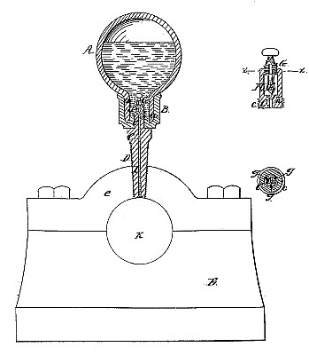
Our invention relates to that class of devices which are employed for the purpose of lubricating the shafts of machinery, &c. and our improvement consists in providing either the upper or lower end of the stem of the lubricator with an adjustable valve or cut-off, whereby the flow of oil may be regulated so as to suit the various sizes of journal-bearings, and the different velocities at which they may bo required to rotate.
Claim:
The operation of our improved lubricator is as follows:
The revolution of the shaft K draws the oil down through the duets g, chamber H, and axial channel I, thus keeping said shaft constantly and uniformly lubricated.
The amount of oil which flows from the globe may be regulated as, occasion may require, by elevating or depressing the valve F, so as to increase or diminish the area between it and its seat, h, which elevation or depression is effected by simply rotating said valve either to the right or left.
In the drawings the valve is shown as being located in -the upper end of the stem, but it is evident that it may, if preferred, be seated in the lower end of the same.
A modification of our improvement may consist of a cut-off, constructed in the following manner: One or more apertures or slots may be drilled through the sides of the stain C, so as to communicate with the chamber near its lower end, and the interior of said chamber may be screw-threaded to receive a plunger or cutoff and by elevating or depressing said plunger, thereby partially or wholly uncovering said apertures, the oil will permitted to flow through them in a less or greater quantity.
(16) We claim herein as new and of our invention the combination and arrangement, substantially as described, of the globe A a, socket B, tubular stem Ja I D, chamber H h, and valve F G g, |
|

)
)