|
Description: |
| Most of the patents prior to 1836 were lost in the Dec. 1836 fire. Only about 2,000 of the almost 10,000 documents were recovered. This is one of the recovered patents. This patent is in the database for reference only.
Text of patent 6323X:
M. D. Mann & S. Sturdevant
Type Casting Mach.
3 sheets of drawings followed by 5 handwritten pages of text.
Text page 1 - first line added in 1970s
6323X Jan. 7, 1831
Michael D. Mann & Stephen Sturdevant
Letters Patent Dated January 7th, 1831
---------------------------
The Schedule referred to in these Letters Patent, and making
part of the same, containing a description in the words of the
said Michael D. Mann and Stephen Sturdevant, themselves of
their improvement in the machine for casting printing type, cal-
led a Vertical Type Caster, which Invention they have assigned
to Elihu White of the City of New York, which assignment is
recorded in the Patent Office in the book of Transfers Vol. 3 Page
365.
-----------------------------
To all to whom these presents shall come. Be it known that
Mr. Michael D. Mann and Stephen Sturdevant, Machinists
of the City, County, and State of New York, have jointly inven-
ted, constructed, and applied to use a new and useful Machine,
for casting Printing Type, not before known, which we call
the Vertical Type Caster. A description of the construction
and manner of using said machine is correctly set forth by the
accompanying drawings, and specification, in the words fol-
lowing to wit.
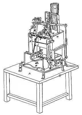
(A) In drawing Fig (1) represents the leaf of a table on which
the Machine is planted. (BB) risers, on which a metal bed piece
marked (C) is secured. (D), A movable metal platform lying
immediately over bed biece (C) resting on the ends of four
levelling screws,and fixed to the bed (C) by nut and bolt
in the middle.
(E & F) Side posts cast on, or secured to the platform (C). (G), A shaft
centered on each end resting and turning on centres, which are
fixed in the head of the posts (E & F). On this shaft is secured
the fixed arm (H), and the socket joint, which hold in centres, the
the movable arm (I). Near the middle os said shaft is fixed the
6323X 2/5
arm (J). Below the shaft (G), rests the shaft (K) fitted to revolve
on journals, the boxes of which are formed on the side posts (E & F).
To this shaft is attached the crank (L), the snail(?) wheel (M), and an
elliptical eccentric cam (N), to the two projecting arms of which
at 1,2, is secured an elliptical rim of iron, so as to form round
cam (N), an elliptical groove or channel. From the platform
(D), rises the stud (O), to which is hung by a joint and pin, one
end of the lever (P). A pitman marked (Q) is coupled by a pin
and joint, to the other end of said lever and likewise to the
end of arm (J). From the lever (P), projects within the ellip-
tical groove, a pin having on it a friction roller (?), round
which travels the aforenamed elliptical rim. On the post
(F) is secured a swivel socket, marked (R) through which passes a pin
formed on the end of the coupling rod (S). The other end of this rod
plays through a fixed socket formed in a projection of the side
of arm (I), and is prevented from being drawn out of the sock-
et, by a nut on the end of it.(T) An iron reservoir, or metal
kettle, the bottom and sides of which are enclosed by an
iron fireplace, marked (U), having a grate for the fuel, a door
on one side, and a smoke pipe (12), the whole supported on ris-
ers, planted on the leaf of the table.
(4 & 5), Side posts to an iron gallows frame, the feet of which
are secured by screws to the rim of the reservoir, the cross piece ly-
ing directly over it. In a piece of iron secured on the top of
this cross piece, a socket is made, through which passes the
upper end of a piston, or pump rod marked (V). Through
said rod a mortise is cut at (V) through which passes the lever
(W) one end of which is secured by a pin at (x), to an arm end (?)
on and projecting out from post (4) of the gallows frame.
From the platform (D) rises a stud (X) slitted at the upper
end to receive the lever (Z), in which it is secured by a pin.
The levers (Z) and (W) are coupled together by the rod (6) having
3/5 6323X
a joint and pin at each end of it, at one end of the lever (Z) is
fitted a friction roller resting against the snail wheel (M). In
the end of the arm (I?) is a socket of about three inches deep, and
3/4 (?) of an inch diameter is bored. (7) A bit of iron, about one inch
square, at one end of which a shaft of three inches long is turned,
and is slid into the before named socket. This piece so fitted
we call a slide arm. It is held to its place by the thumb screw
(17). For the iron (11?) and the slide arm (7), we make and attach
a set of clamp hooks, see Fig (3?). To each back plate of a com-
mon Type Mould we screw a piece of iron, of the length of said
plate and of about 3/4? by one inch square, in the upper and
under sides of which a groove is formed to receive the hooks
of the clamps (8.8.8.8.). By means of these clamps, and the
screw (g) one half of the mould in which the type are to
be cast, is secured to the arm (H), and the other half to the
slide arm (7). (10) A bent lever having its fulcrum at (11),
and working over a pin at (13). Its use is to lever or raise one end
of the matrix, before discharging the type from the mould.
(14). A spring one end of which is to rest on the matrix, and
keep it to its place, when the type is cast. The other end is se-
cured to the arm (H). (15) A spiral spring by which the piston rod
is forced downwards. (16) A nut against which the spring rests.
This nut works on a screw formed on the piston rod, and by this
nut and screw the force of the pump can be regulated.
Fig (II) A section shewing the inner formation of our reservoir or
metal kettle. In the right column (a.a) which is cast to,
and rises above the bottom of the kettle, the chamber (c) is formed
from which the passage (d) leads through the lateral projection
(e) also cast on the bottom of said kettle. This passage con-
nects with and has its outlet through the passage (f) formed
in the projection (g) cast on the inner side of the kettle. In the
chamber (c) is fitted the piston (h) bored through the center
4/5 6232X
rod (i?). It will also be seen that by the depressing one end of the
lever (Z) the piston rod (V) will be lifted, and that a further
turn of the snail, will allow the lever (Z) again to rise from
the joint of the snail, and the piston to settle down, which it
instantly will do, from the action of the spiral spring (15); the
fall of the piston will drive a jet of metal up through the
spout into the mould: a still further turn of the crank, again
depresses lever (Z), and lifts the piston, and also raises the mould
from the spout by means of the lever (P), cam (N), and
elliptical ring.
As the mould rises, the rod (S), will cause it to open, and the
opening of the mould, will bring the type in contact with
a hook or hooks (see 13?) placed on one or both of the arms (HI)
as may be found expedient, by which it will be discharged
from the mould. But we are not alone confined to the
before described manner of forming and hanging the swinging
arm (I) of our machine. Nor to the before described form of the shaft
(G), or mode of giving motion thereto. By making shaft (G), in the
form of a cross, and a ring at the end of arm (I), we hang this arm
to swing on centres, passing though the ring into the arms of the cross
(see Fig. VII); and in the place of hanging the shaft (G) on centres as
before described, we make it to turn on journals formed at the top of
the side posts (E & F) and passing shaft (K) through said posts direct-
ly under shaft (G), see Figs (IV & V) we dispense with the cam (N), the
rod (g)
elliptic ring, the stud (O), lever (P) and arm (J) before described, and
placed on the end of shaft (K) the compound swivel(?) crank (y) and
between two friction rollers on said crank, we place the curved end
of lever (r) the other end being secured to the end of shaft (G) so
that by turning the crank (L) and shaft (K) we give the same mo-
tion to the shaft (G) and the arms thereto attached as before described.
The compound crank (y) can be shipped or unshipped from the
lever (r) by sliding the shaft (K) backwards or forwards in its
6323X 5/5
sockets, the snail wheel (M) being made wide to prevent the unshipping of
. . lever (u)(n) a dog for holding shaft (K) in its place.
Summary of what we claim and specify as our invention and improve-
ment in the above described machine, namely, First, The particular con-
struction of the above described kettle, so as to admit of working the mould
directly over its rim, and of taking the metal out of the kettle, through
a spout rising above said rim. Secondly. The rolling spout and cor-
responding Counter Seat by which the face of the spout is adjusted with
requisite exactness to the face of the mould to prevent the escape of
metal when ejected into the mould.
Thirdly. The mode of casting by a perpendicular jet of metal conducted
from the metal kettle into the mould, through a spout rising above
the rim of the kettle.
Fourthly. The construction and mode of hanging the two arms of the
machine, to which the type mould is attached, and the mode of working
the type mould, when secured to the ends of said arms.
Fifthly. The application of clamps to a grooved back piece, on the
back of the mould, for holding the mould to the arms of the ma-
chine as before described.
Sixthly. The mode of opening and closing the mould by means of the rod (S) and the socket (R) as before described.
Seventhly. And we further claim as our invention and improve-
ment, the above described new arrangement and combination of differ-
ent parts of the whole machine by which a great improvement is ob-
tained in casting printers Type.
In testimony that the above is a true Specification of our said above
named invention we have hereunto set our hands this 22d day of
December in the year of our Lord One thousand Eight
hundred and thirty.
Witnesses M. D. Mann
Nathan Lyman Stephen Sturdevant E.O.(?)
William C. Lyman H.K.(?)
Text and patent images courtesy of Mark K. Digre.
|
|

)
)
)
)
)
)
)