|
Description: |
| Abstract:
My invention relates to a gas or oil engine, my object. being to provide means for opening and closing the exhaust-valve, and, furthermore, to provide a pump adapted to be actuated at proper intervals to force the oil into the ignition or mixing chamber.
In gas-engines, as usually constructed a working stroke occurs only during each alternate cycle, an explosion taking place, which drives the piston forward, the return stroke of the piston being utilized to eject the exploded gas from the cylinder, while a second stroke creates a suction to draw a fresh supply of gas and air into the cylinder, the explosion taking place upon the subsequent return of the piston to the initial position. Since the exhaust-valve must be opened only on each second stroke, some means for causing the opening of the valve once during each two strokes must be provided, and it has been usual to employ gear-wheels for securing the proper movement. It is the object of my the opening of the exhaust-valve at the proper time without the employment of gear-wheels, which are troublesome and hard to keep in repair, and I utilize the pressure within the cylinder for effecting, through intermediate mechanism, the opening of the exhaust-valve.
In the preferred form or my invention I employ a cam mounted upon the main shaft of the engine, the cam being adapted to engage a roller carried -upon the end of the longitudinally moving valve rod, which carries the exhaust-valve; The valve-rod is made in two parts, the one carrying the roller being adapted to continuously move to and fro, while the part carrying the valve remains normally at rest, being moved only when a pin or projection is inserted between the two parts, whereby the longitudinal move the accompanying drawings, forming apart of invention to secure parted to the portion upon which the valve is mounted. In order to secure the interposition of the pin or projection between the two parts of the valve-rod at the proper moment, the pin is connected, through-intermediate opened at the proper time to permit the escape of the exploded gases. I also utilize the varying pressure within the cylinder of the engine for operating the pump which forces the oil into the ignition-chamber. Au admission-port is provided through which the air and oil are admitted into the mixing-chamber, the port being normally closed by a valve, which, when a partial vacuum is formed within the cylinder as the piston moves forward, is drawn from its seat by the suction, thus opening the port for the admission of the air and oil. The plunger for the pump is connected with the valve, so that as the valve moves, due to the suction, the plunger is thrust into its barrel to force the oil into the ignition-chamber.
I provided a governor, which responds to changes of speed for controlling the stroke of the pump, the governor preferably acting to vary the tension of a spring opposing the movement of the inlet-valve, the pump-plunger being mounted to move with the inlet valve. The extent to which the pump-plunger is moved by the inlet-valve thus depends upon the tension of the spring. In practice I find it desirable to provide for a slight freedom of movement between the pump-plunger and the inlet-valve, so that when the speed is a maximum and the inlet-valve is unable to move the pump-plunger against the tension of the spring the inlet-valve may move relatively to the pump-plunger to permit the partial opening of the inlet-valve and thus admit air to the cylinder; otherwise the engine-piston would create a vacuum, thus necessitating the waste of considerable power in moving the piston forward. The governor acts constantly upon the inlet-valve and the pump plunger, the tension of the spring being continuously varied in exact accordance with the change of speed of the engine. The governor is thus of the continuous-contact type as distinguished from that class in which the governor acts at intervals to control the speed according as it rises above or decreases below definite values. By the employment of a continuous-contact governor the quantity of explosive material drawn into the cylinder is exactly proportional to the power to be developed.
Claims:
1. In a gas-engine, the combination with the exhaust valve and actuating .connections therefor, of .a cam of irregular periphery mounted upon the main shaft of the engine, a short portion of the periphery of said cam being adapted to lock and maintain said actuating connections of the valve in operative position, another and longer portion being adapted to open the valve, and the remaining and longest portion permitting the closing of the valve and the release of the actuating connections thereof, substantially as described.
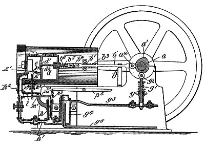
2. In a gas-engine, the combination with ignition-chamber e of the exhaust-valve d', slotted casting c, rod b5 connecting the exhaust-valve d' and the said casting, piston c7 moving in cylinder c8 by the force of the explosion in -he ignition-chamber, pin e2 actuated by the movement of the said piston to enter within the slot in casting c in the path of valve-rod b, valve-rod b' extending within the slot in casting c and cam d of irregular periphery mounted upon the main shaft of the engine, a short portion of the periphery of said cam being adapted to lock and maintain the actuating connections of the valve in operative position, another and longer portion being adapted to open the valve, and the remaining and` longest portion permitting the closing of the valve and the release of the actuating connections thereof, substantially as described.
3. The combination with a cam mounted upon the shaft of the engine, of a part carrying a cam-roller adapted to engage said cam and to be reciprocated thereby, an exhaust valve, a longitudinally movable part upon Which said valve is mounted, a slot carried in the end of one of said parts within which a tongue carried upon the other part is adapted to move, a pin to be inserted into said slot in the path of said tongue, an auxiliary cylinder in communication with the engine cylinder and connected with said pin, substantially as described.
4. The combination with a rod b5 carrying the exhaust valve, of the casting c mounted upon the end thereof and carrying slot c', said casting having a slight freedom of movement relatively to the exhaust-valve, the tongue b4 adapted to be reciprocated in the slot c', the pin c2 adapted to be moved into the slot in the path of said .1'.ongue,` and, the cam a for reciprocating said tongue and having the' concentric portion B' C adapted to maintain the end of the tongue in engagement with the pin c2 without imparting longitudinal movement to the rod b5; substantially as described.
5. The-combination with a part adapted to be moved by the suction within the engine cylinder, of a pump-plunger operated thereby, a spring opposing the movement of' said plunger, and a governor for regulating the tension of said spring; substantially as described.
6. The combination with an inlet-valve adapted to be moved by the suction within the engine-cylinder, of a pump-plunger operated thereby, and a governor for regulating the movement of the plunger and the inlet-valve to control the quantity of explosive mixture admitted to the engine-cylinder; substantially as described.
7. The combination with an inlet valve adapted to be moved by-t he suction within the engine-cylinder, of a. pump-plunger, a spring opposing the movement of the inlet-valve and the plunger, and a governor for varying the tension of said spring to control the quantity of explosive mixture drawn into the engine cylinder; substantially as described.
8. The combination with an inlet-valve operated by the suction within the engine cylinder, of a pump-plunger moved by said valve, a governor for controlling the strokes of the pump-plunger and of the inlet-valve, and means for permitting a slight freedom of movement of the valve relatively to the plunger to admit air to the engine-cylinder when the plunger remains at rest substantially as described.
9. The combination with a longitudinally movable wheel or disk mounted upon the engine-shaft, of a wedge interposed between said wheel and a part mount stationarily upon the engine-shaft, said wedge when moved serving to impart longitudinal movement to said wheel or disk, a governor-ball for moving said wedge, a controlling lever continuously in engagement with said longitudinally movable wheel and adapted to be operated by the longitudinal movement of said wheel, a pump-plunger, and an inlet-valve, the stroke of said plunger being controlled by the movement of said operating lever; substantially as described.
10. The combination with a longitudinally movable wheel or disk mounted upon the engine-shaft, of a wedge interposed between said wheel and a part mount stationarily upon the engine-shaft, said wedge when moved serving to impart longitudinal movement to said wheel or disk, a governor-ball for moving said wedge, a controlling-lever continuously in engagement with said longitudinally movable wheel land adapted to be operated by the longitudinal movement of said Wheel, and an inlet-valve the stroke of which is controlled by the movement of said operating-lever; substantially as described.
11. In a gas-engine, the combination with the ignition-chamber e, of the exhaust-valve d', slotted casting c, rod b3 connecting the exhaust-valve and the said casting, piston c7 moving in cylinder c8 by the force of the explosion in the ignition-chamber, pin c2 actuated by the movement of the said piston to enter within the slot of casting c in the path of valve-rod b, valve-rod b extending Within the slot in casting c, cam a mounted upon the main shaft of the engine, the periphery of said cam being provided with portions A' C', C' D' and D' A', the latter portion being respectively of increasing and decreasing radius, a short portion of the periphery A' C' being adapted to actuate the valve-rod to lock and maintain pin c2 in position when the said pin is forced Within the slot, portion C' B, being adapted to open the valve, and the longer portion B'A' permitting the closing of the valve and the release of the actuating connections thereof, substantially as described,
See patent #740,571 for an improvement to this patent.
|
|