|
Description: |
| Most of the patents prior to 1836 were lost in the Dec. 1836 fire. Only about 2,000 of the almost 10,000 documents were recovered. Little is known about this patent. Only the patent drawing is available. This patent is in the database for reference only.
“Specification of a patent for a new and improved mode of causing Rail-way Carriages to run with equal facility on straight or curved roads; denominated the Self-adapting Rail-way Carriage, or Car. Granted to James Wright, Columbia, Lancaster County, Pennsylvania, September 10.
Be it known, that I, James Wright, of Columbia, in the County of Lancaster, and State of Pennsylvania, have invented a new and improved mode of causing rail-way carriages to run with equal facility upon straight or curved roads; which carriage, or car, so constructed, I denominate the Self-Adapting Railway Carriage, or Car; and that the following is a full and exact description of my said improvement.
The wheels are firmly fixed upon the axles of the carriage; the axles turning in suitable boxes, or against friction wheels, constructed in any of the modes already known. The bearings in which the axles run, are attached to the frame work of the carriage, by a bolt, or pin, in their centres, in order to admit of such a degree of motion, or vibration, on these centres, as shall allow of the fore and hind wheels adapting themselves to the curvature of a road, by their planes forming a tangent to the curve of the rail upon which they are to run.
The wheels have each one flanch, and their edges, which run upon the rail, are in the form of the frustum of a cone, the flanch being upon the side of largest diameter, which usually stands within the rail, but it may be placed on the outside, without, in any way, vary. ing the principle upon which it is to operate.
The angle which the edge of the wheel forms with its plane, may admit of considerable variation, and may be governed by the radius of the smallest curvature over which the carriage is to pass; as for example, should the curvature be upon a radius of three hundred feet, the angle will vary more from ninety degrees, than would be necessary for a curvature of six hundred feet. In every case the obliquity must be such, that in running upon the rails, a circumference shall be found upon the conical surfaces of the wheels, which shall adapt them to the running, without friction, upon each of the curved rails.
The kind of rail which I would prefer as best adapted to my improved carriage, is the round topped rail; but any of the rails in ordinary use may be employed.
When a carriage, constructed in the manner above described, is placed upon a rail-road, it will be found that it has a tendency to adjust itself; and actually will adjust itself, so as to give to the wheels the positions necessary for running upon a road, either straight or curved, with no other than the ordinary rolling friction.
What I claim as new, and for which I ask an exclusive privilege, is the conical form of the edges of the wheels, and the vibratory motion of the axle, to allow of the wheels adapting themselves to the curvature of the rails.
Where, in any particular part of a road, it is desired to turn upon a smaller curve, than might be thought convenient by the foregoing plan, the addition of a rim may be made to the wheels, to operate upon an elevated rail, upon the principle described by me in the specification of a rail-way, and cars to run thereon, for which a patent was granted to me on the 17th day of April, 1829.
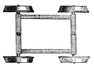
In the annexed drawing, Fig. 1 represents the plan of the carriage; and Fig. 2, the connection of the axle with the carriage by means of a pin through its frame, and the frame in which the axle turns. Between the two frames friction wheels, or rollers, may be placed to sustain the load, and allow the axle to vibrate freely.”
Journal of the Franklin Institute Vol. 7, Oct. 1829 pgs. 272-273
|
|

)
)