|
Description: |
| Most of the patents prior to 1836 were lost in the Dec. 1836 fire. Only about 2,000 of the almost 10,000 documents were recovered. Little is known about this patent. There are no patent drawings available. This patent is in the database for reference only.
“Description of an Improved Wheel with Revolving Padilles, applicable to the propelling of Ships and other floating bodies. Patented by Adolph Heilbronn, New York, March 16th, 1829.
In the patent of Mr. Heilbronn, several different improvements in navigation are described and claimed; in the present article, we shall explain the first of them only, but shall hereafter present the others, having a plate prepared for that purpose.
These various inventions have been perfected in conjunction with a gentleman in England, where a patent has also been obtained for them.
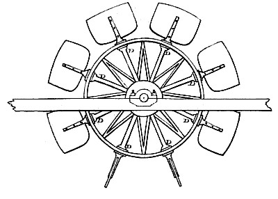
The revolving motion given to these paddles, differs altogether from that which has been contrived with a view to their dipping into, and emerging from the water vertically. The paddles, or buckets, in Mr. Heilbronn's wheel, are each fixed upon an arm which radiates from the centre of the wheel, as may be distinctly seen by a reference to the engraving.
In a wheel so constructed, the paddles may be made to enter the water edgewise, and be turned, so as to act upon it at any point which may be preferred. The paddles which are out of the water, are all feathered, or turned edgewise, so as to experience but little resistance from the wind, and to require a very shallow box or casing, to protect them on each side of the boat. A wheel of this description may be immersed in water to any depth which may be required; or it may be entirely under water, where the depth is sufficient; should such a mode of fixing it be thought advisable, the progress of the boat will be but little impeded thereby.
One great advantage anticipated from these paddles, is the avoiding of those numerous and perpetual concussions produced by the striking of the water by the ordinary floats, which causes a continued, distressing, and very injurious tremulous motion. They enter by their edges, and are gradually brought into action.
The number of revolving paddles to be used will be best determined by experiment.
Figure 1, plate 2, represents one of the said wheels of eight arms or paddles, as it appears when in a finished state, and as applied to the side of a vessel; and figure 2 is a view on a larger scale of the central part of the said wheel, as seen from the opposite side, or that nearest to the vessel, for the purpose of showing how the paddle-arms are held and supported in their places, and yet permitted to turn or feather at the proper instant, while the whole wheel turns round; and figure 3 is a section of the same part of the paddle-wheel, as is shown by figure 2, and likewise of the piece G'G, which is called the wiper carriage, which is immovably fixed to the side of the vessel, for the purpose of producing the turning or feathering of the paddles at the proper moment. In these several figures A A A A, is a circular disk or plate of cast-iron, having a rim or ring B B B, rising on one side to a sufficient height to give strength and solidity to the said circular plate, and also to take the brasses C C C, through which the paddle-arms or axes D DDD), are permitted to turn. The central block of metal E may be cast in one piece with the disk or plate, but will be better detached, and afterwards fixed to it by screw bolts, as shown in the section figure 3, because when detached, the brass sockets, or steps a a a a, for receiving the inner ends of the paddle-arms or axes, can be more accurately bored and fixed. The disk or plate A A A A, with its centre block E, forms the central part of the paddle-wheel, which must be firmly keyed, or otherwise fixed upon the main shaft F F, which derives its rotary motion from any power applied within the vessel, and this shaft also passes freely through the centre of the metal wiper carriage G, which is firmly and immovably fixed to the side of the vessel, for the purpose of operating upon the wipers or projections b b of the paddle axes, in order to produce the turning or feathering of the paddles. To effect this, the outer face of the wiper carriage presents two annular surfaces, as seen at c and din figure 4, (which is a front view of it,) and a part of one of them is cut away as at e e, to a greater or less extent, according to the period at which it may be desirable to make the paddles turn or feather. The wipers or projections on the axes of these paddles are projections of steel or other metal, crossing each other so as to project at right angles from the axes of the paddles, and as these wipers come into contact with one or other of the annular surfaces c and d, figure 4, and also seen in figure 2, the several paddle axes will each make a quarter turn or revolution. Thus the five wipers z z z z z, figure 2, lie with their flat surfaces upon the annular surface c of the wiper carriages, but that surface is cut away between e and e, (as is more distinctly seen in figure 4,) and the inner annular surface d then presents itself, and acts upon the wipers z z to turn them round; consequently the inner wipers y y y will now assume the flat position, and will continue in it, until they are again brought by the motion of the wheel, into contact with the ends of the outer annular surface c. It will thus be seen, that by enlarging or contracting the opening e e, figure 4, and with it the inner annular surface d, that one, two, or more, of the paddles may be made to stand at right angles to all the rest, and thus that any number of paddles may be made to move through the air, and to enter into and come out of the water with their thin edges forward, while the remainder, or those that are under the water, will remain steadily in that position in which they are most effective for the purpose of propelling, as is distinctly shown by the manner in which the paddles are arranged round the wheel, as shown by figure 1. It will be necessary to employ springs to prevent the blow and concussion, which would otherwise take place between the wipers on the axes of the paddles, and the ends of the wiper carriage upon which they strike, and by which they are turned round; and the best application of such springs, is to use those of the spiral kind, of considerable strength, and to introduce them into round holes very nearly fitting them, and drilled in the ends of the wiper carriage which first comes into contact with the wipers. The spring being introduced into the hole, a cylinder of hard steel just fitting the hole is placed upon it, and there fixed by a pin driven through a chased mortise hole in the said cylinder, in such manner that the said cylinder can fall wholly into the said hole when pressed upon, but without such pressure, will project about half an inch or rather more out of the said hole; and as the said wheels are so fixed as to require cases to protect them, as in ordinary steam-boats, such cases may be formed of light iron work, covered over with slight iron bars, or with strong wire work, because such open work cases do not offer the same resistance to the wind and water as close boarded cases do; and moreover, they have the effect of much more effectually breaking the force of the waves when they drive against them.
Bars or rods with points upon them are also fixed to the insides of such cases, causing the said points to come as nearly as possible to the paddles and paddle axes without touching them, for the purpose of clearing off any weeds that may attach to the paddles, and likewise to protect them from striking against any timber, ice, or other floating substances, by which the paddles of steam-boats are frequently broken or injured.
The claims of the inventor, in the paddle wheel and its appurtenances, are, First, to the frame work, or wheel, as above described, for holding the patent paddles. Secondly, the introduction of springs to act upon the wipers. Thirdly, the paddle box made of open wirework, net, or cross bars, with projecting pieces, or points, to clear the paddles.
Experiments are now in progress in New York, for testing the value of the foregoing machinery. The trials hitherto made have been attended with satisfactory results; but experience teaches us to suspend a final judgment until the thing is fairly tested, in a vessel of the ordinary size.”
Journal of the Franklin Institute Vol. 6, Sept. 1829 pgs. 194-197
|
|

)
)
)