US Patent: 426,511
|
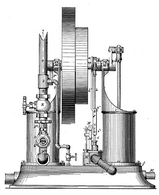
| Steam Pump and Motor
|
|
Patentee:
|
|
| Fred C. Olin (exact or similar names) - Buffalo, NY |
| Manufacturer: |
| Not known to have been produced |
|
|
Patent Dates:
|
| Applied: |
Nov. 09, 1889 |
| Granted: |
Apr. 29, 1890 |
USPTO (New site tip)
Google Patents
Report data errors or omissions to steward
Joel Havens
"Vintage Machinery" entry for Olin Gas Engine Co.
|
|
Description: |
| Michael J. & William O. Stark - patent attorneys
The operation of this steam pump and motor is substantially as follows: Assuming the parts to be in the position shown in Fig. 2; that is to say, all the valves closed and the steam-piston at its apex and at the moment of commencing its down-stroke. The beam R has up to this point traveled a distance equal to the length of the slot-hole in the valve-rod r, so that as soon as the steam-piston starts on its down-stroke the puppet-valve S (being the exhaust-valve) opens and allows the steam to escape into the suction-chamber U, which, it is assumed, is filled, or at least partly filled, with water either from priming it or from the action of the pump, where said steam will be immediately condensed, and thereby cause the down-stroke of the steam-piston by atmospheric pressure, and at the same time assist in drawing water into the suction-chamber through the suction-pipe E', This pump-piston acts both as a sucker for the water to be raised and as an air-pump for the condenser, it drawing from the suction-chamber TJ, and thereby drawing with the water also the air and other products resulting from the condensation of the steam. The suction-valve chamber Y is carried down nearly to the bottom of the suction-chamber TJ, so as to draw therefrom as much as possible of the water and air contained therein. This is quite an essential feature to secure regularity in the action of the pump, which would not be so readily attained were the suction-chamber kept more or less full of the water of condensation. Owing to the partial vacuum in the suction-chamber during the down-stroke of the pump-piston, when water is being forced, water will be drawn into the suction-chamber through the suction-pipe E' during that stroke, so that as soon as the steam-cylinder exhausts its steam, will immediately come in contact with the fresh and cold water in said suction-chamber. When the steam-piston has nearly completed its down-stroke, the puppet-valve S will seat, while the rod i, connected with the puppet-valve I, will have moved the length of the slot-hole i', so that as soon as steam-piston. 0 has completed its down-stroke and just begins its upstroke, said puppet-valve I will open and allow steam to enter the steam-cylinder by the passage v, which also forms the exhaust-passage for the steam after the completion of the upstroke. A repetition of the operations heretofore described causes the continuation of the operation of the machine, a fly-wheel Q, having a band-wheel Q', assisting in carrying the cranks over their dead-centers. It will now be observed that the water-pump by the pump-piston forms the medium to condense the steam used in the steam-cylinder. Should it be required to use high-pressure steam in the steam-cylinder to lift water from a certain height, I shall regulate the length of the slot i' in the valve-rod i, so that the puppet-valve I will close early in the upstroke of the steam-piston, and thereby allow of an expansion of the steam sufficiently, so that when the upstroke is completed the initial steam-pressure shall have been reduced to a comparatively low one, and so that this steam will be readily condensed by the water in the. suction-chamber TJ without raising its temperature to any great extent, although steam at a high pressure will be condensed by said water if necessary. To use the steam-pump as a motor or engine only, the suction-pipe E' must be closed by a valve, (not shown,) and the discharge-pipe closed by shutting the stop-valve 2 and by opening the stop-valve 1, the pipe G of which should be connected with a sewer, reservoir, or other suitable receiver for the water of condensation, resulting from the operation of the engine, and which is not intended to be forced into the receptacle into which the pump when in use will deliver its water, and then the stop-valve Y' opened to discharge into the suction-chamber TJ, with water which will now come from the said reservoir into which the pump delivers its water or which might be supplied from a street-main or other suitable source. If steam is now given to the steam-cylinder, the operation of the steam-piston and its accessories will be the same as heretofore described; but its exhaust-steam will now be condensed by the sprays of water issuing from the perforated pipe Y, and removed from the suction-chamber by the pump acting in this case as the air-pump only. It will thus be seen that the change from a steam-pump to a steam-engine is one that can be made in a few moments of time, so that this machine is admirably adapted for farm and similar purposes, where it will only for a short time be used as a pump and may then be run as a motor. One of the advantages of constructing the pump and motor as described is, that the condensed water always carrying with it a to certain portion of air, the air in the air-chamber will constantly be replenished, it being a fact that in water-pumps having air-chambers the air is frequently forced out of said chambers, and then fails to properly perform its predesigned function. So does the suction-chamber act as an air chamber for the suction-pipe, for the reason that it will never fill entirely with water when the engine is running even at a slow speed.
|
|