US Patent: 325,233
|
| Micrometer Caliper
|
|
Patentee:
|
|
| Merrick M. Barnes (exact or similar names) - Boston, MA |
| Manufacturer: |
| Not known to have been produced |
|
|
Patent Dates:
|
| Applied: |
Feb. 04, 1885 |
| Granted: |
Sep. 01, 1885 |
USPTO (New site tip)
Google Patents
Report data errors or omissions to steward
Joel Havens
|
|
Description: |
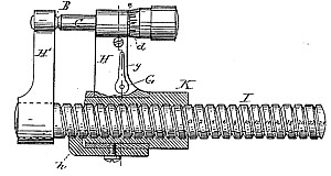
| My present invention relates to micrometer calipers substantially of the character represented in Letters Patent of mine, No. 271,401, in which a micrometer-caliper is so arranged that it may be moved toward or away from its calipering anvil. The object of my present invention is to provide improvements in such devices. In the drawings, Figure 1 represents, in elevation and partial section a device embodying my present improvement and Fig. 2, a vertical section thereof upon the section-line indicated in Fig. 1. Fig. 3 represents the obverse of Fig. 1, and shows more fully the graduation of the shifting-screw. In the drawings, H represents an arm carrying a micrometer-calipering device, C D, this arm being so arranged that it may be moved toward or away from another arm, H', carrying the anvil. I obtain this motion of the calipering arm by mounting it upon a shifting-screw, I, a nut, K, being interposed between the arm H and screw I, so that by turning this nut in either direction the desired motion of the arm may be obtained. The arm is prevented from turning by a tail, h, entering a spline on the screw I, as shown. By regulating the pitch of the screw I, and properly graduating it with reference to a zeromark on the nut K, I obtain a convenient device for measuring the precise distance of motion of the arm H. It is obvious that the arm H might be itself directly threaded upon the screw I, but this construction would involve swinging the arm around the screw, which is often objectionable. The calipering device shown at C D represents the form shown in my Letters Patent No. 271,401. It is, however, obvious that other forms of calipering-screw may be substituted for it. I have also shown and described the graduated shifting-screw only as shifting the calipering-screw relatively to a fixed anvil. It is obvious that the same screw might be arranged to move the anvil relatively to the calipering-screw, the latter remaining stationary. Such a construction, though practically defective, would, nevertheless, embody my present invention to the extent of employing a graduated shifting screw as a means of altering the field of action of a calipering-screw relatively to its opposed calipering-anvil, when either is carried by a movable arm operated by said shifting-screw.
|
|