US Patent: 3,168,005
|
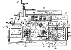
| Shaping Machine
|
|
Patentees:
|
| Granger Davenport (exact or similar names) - Berlin, MA |
| Theodore R. Crocker (exact or similar names) - Bound Brook, NJ |
| Manufacturer: |
| Not known to have been produced |
|
|
Patent Dates:
|
| Applied: |
Oct. 17, 1960 |
| Granted: |
Feb. 02, 1965 |
USPTO (New site tip)
Google Patents
Report data errors or omissions to steward
Joel Havens
"Vintage Machinery" entry for Norton Co.
|
|
Description: |
| Lewis M. Smith Jr. - patent attorney
This invention relates to improvements in machine tools and their drive transmissions and more particularly to an improved method and means for operating a shaping machine. The conventional shaper comprises a box-like frame with horizontal guide ways along its top and vertical guide ways along its front. A cross rail member having horizontal work-table-carrying guide ways along its front is mounted on the vertical guide ways of the frame and a tool-carrying ram member is mounted for reciprocation on the top guide ways of the frame. The work piece to be machined is mounted on the work table and on each forward stroke of the ram the tool carried at its forward end engages the work and planes or shapes off a portion thereof. On the return stroke of the ram, the work table is propelled laterally or vertically as the case may be, a unit increment so that on succeeding forward strokes of the ram the tool operates successively upon new areas of the work piece. When the work surface has been machined to the required extent, the worktable is back traversed to the point of starting and the cycle is repeated upon the same or another work piece. In the earlier types of shapers the machine was driven by overhead belts and started and stopped by shifting the drive belt. Later, an electric motor mounted on the machine operated through a main friction-type clutch to drive the machine. The clutch was designed for manual operation and considerable effort was required to operate it to bring the machine to a stop. It was also common practice to equip the shaper with a lubricating pump that received power from the motor at a point ahead of the main friction clutch. Hence, whenever the motor was started, the pump was driven continuously and furnished lubricant to the numerous gears and elements in and upon the main frame before the clutch was engaged to drive the machine. For a few years it was popular to take power from the continuously running pump drive to operate the work table feed screws selectively at a traverse rate, usually in a direction opposite the intermittent feed that came from the ram drive train, so that the work could be back-traversed quickly to the starting point. Considerable difficulty was, and continues to be, experienced with friction-clutch drives, one difficulty being the inability of the clutch to pick up the load in the event the operator has stalled the tool in the cut, and another being that the inertia of the ram tends to drive the clutch backwards on each ram reversal with consequent destructive effects upon the clutch. Increasing the size of the clutch did not provide an answer, for that not only created bulky design problems, but resulted in too great a jolt to the machine whenever the clutch engaged. The main purpose and objective of this invention is not only to provide a practical solution to the perplexing problems that exist with the use of friction clutches in shaper drives, but to increase the efficiency of the shaping machine by the development of an improved drive and operational method. A further aim of the invention is to render available a shaping machine wherein ram speeds and work table movements are more easily controllable, as for example, by pushbuttons that require a minimum effort on the operator's part for their actuation. Still another aim of the invention is to provide a machine in which the full power of the drive motor is available at all times to propel the ram and to propel the work table incrementally. The invention has for a further object, the provision of a machine-tool transmission in which the clashing of teeth of shiftable gears is reduced to minimum pro5 portions. Most of the time the teeth of shiftable gears will line up or find themselves on shifting. Occasionally and notwithstanding the rounding of the leading ends of the teeth, a set of gears will meet dead on. If there is a main clutch in the drive, the instantaneous start incident to the engagement of a clutch with a running motor causes the gears to spin, producing considerable noise and eventually severe damage. However, if in accordance with the basic features of this conception of a machine-tool drive, a main clutch is not used, and the main motor is directly connected to the ram, the restarting of a stopped motor provides just enough delay in starting to allow the teeth of the gears to mesh properly before the motor reaches its normal running speed. The use of a direct-connected main-drive motor also makes possible the conception and provision of an auxiliary motor to drive a lubricating pump that will supply lubricant to needed areas and furnish hydraulic pressure to actuate hydraulic gear-shifting cylinders and clamp, etc. To advantage, the auxiliary motor may be operatively connected also to the work table feed trains to traverse the table up or down, or to the left or right, while the main motor stands idle and the main transmission is immobilized. Motor controls are arranged, as will more fully appear, so as always to cause the auxiliary motor to start operating before the main motor that drives the ram is energized. This conception has the objective of insuring adequate lubrication and pressure in the hydraulic gear-shifting system and hydraulic clamps or the like before the main shaper drive is started. In carrying forward the aims and objectives of this invention, a new shaper design is proposed in which the main motor is built-in within the main frame and directly and permanently connected with the change-speed gearing of the ram-drive and work-table-feed transmissions. The main motor is preferably provided with a magnetic brake or equivalent means to overcome armature inertia and obtain almost instantaneous stopping when the starter switch for the main motor drops out. In conjunction and in combination a second motor is provided, built-in like the main motor, which is permanently connected with a hydraulic pump and also connected to a selector clutch in the worktable feed trains. The arrangement is such that the auxiliary motor is continuously available for traverse movements of the worktable while the main motor is available only for the intermittent feed movements of the worktable. In this connection it may be said that this conception comprehends a system of gearing arrangements in which the rapid traverse movements of the work occur in directions that are always opposite to that of the feed regardless of the direction of the feed. In other words, when the intermittent feed train is disconnected and the traverse train is connected to the table drive element, the table and work thereon always moves away from the cutting tool carried by the ram whether the drive train to the latter is operating or not, provided, of course, the operator does not purposely change the direction of movement by shifting the direction-control lever.
|
|