US Patent: 2,868,268
|
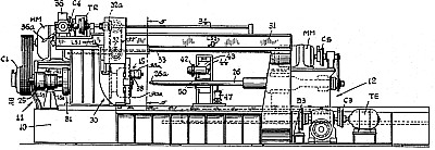
| Coil-Forming Machine with Generator Controlled Spindle Postitioning Means
|
|
Patentees:
|
| Thomas E. Lewis, Jr. (exact or similar names) - Trumbull, Fairfield County, CT |
| Victor A. Zaverruha (exact or similar names) - Trumbull, Fairfield County, CT |
| Manufacturer: |
| Not known to have been produced |
|
|
Patent Dates:
|
| Applied: |
Feb. 04, 1954 |
| Granted: |
Jan. 13, 1959 |
USPTO (New site tip)
Google Patents
Report data errors or omissions to steward
Joel Havens
"Vintage Machinery" entry for Coulter & McKenzie Machine Co., Inc.
|
|
Description: |
| Abstract:
It is an object of the present invention to provide a coil-forming machine capable of winding coils of various sizes and design quickly and accurately.
Another object of the invention is to provide an improved means for locating the winding spindle in a predetermined starting position.
Another object of the invention is to provide an improved chuck for gripping the first end of the stock forming the coil to insure a tight and square first end down to the tapered point without projections beyond the outside diameter of the coil.
Another object of the invention is to provide a coiling machine with a novel mandrel construction which is long-wearing and free-stripping.
Another object of the present invention is to provide accurate control for starting the coil-laying carriage so that the first coil can be made to form any desired flat base extending through any portion up to substantially a complete turn thereof whereby a flat end for the spring may be provided.
Another object is to provide improved stripping means whereby the coil is removed from the mandrel without distortion, change of length or position of turns.
Another object of the invention is to provide a novel method of coiling and controlling the operation of the elements in forming the coil.
A feature of the invention resides in the unique control of the spindle during the reset period by control of the clutch and brake in the drive therefor whereby the spindle can be set to a predetermined starting position quickly and accurately without overrunning the position.
Another feature of the invention resides in the smooth, freely rotatable mandrel which is adapted to receive the coil in any position on the surface, thus eliminating grooving of the mandrel by the repeated winding of the coil on the same surfaces on the mandrel and the necessity to reset the mandrel. The mandrel is rotated during the coiling operation by the stock forming the coil and gripping the mandrel as the stock is being coiled around the mandrel by the rotation of the chuck, thus eliminating the necessity for a drive for the mandrel. Further, since a grooved mandrel is not used to position the coils, the smooth mandrel of the present invention permits infinite variation in coil pitch or turn relations as they are formed thereon.
A further feature of the invention resides in the positive drive for the mandrel to rotate the same relative to the coil wound thereon during a stripping operation which releases the coil from gripping relation with the mandrel and permits the mandrel to be extracted from the coil without distortion of the coil.
A still further feature of the invention resides in the control for the chuck and the lay-down roller for forming the other end of the coil whereby they hold the coil during the initial mandrel extracting operation and resist any distortion of the coil during the initial extracting period.
Another feature resides in the control system which can be manually or automatically actuated during a forming cycle to produce the coil spring as desired.
Claims:
1. In a coil-forming machine, a smooth, freely rotatable mandrel; drive means; a rotatable spindle driven thereby and having a chuck thereon adapted to grip the end of a piece of stock to be coiled about the mandrel, the stock rotating the mandrel as it is coiled thereabout; a feeding carriage having means engaging the stock; means driven by the spindle and including an electrically operated clutch for feeding the carriage along the mandrel as the stock is coiled 'thereabout; switch means controlled by the spindle for rendering the clutch operative after a predetermined partial rotation of said spindle during a coiling operation, comprising a stop switch for the spindle with a first rotary actuating cam member therefor, and a starting switch for the carriage with a second rotary actuating cam member therefor adjustable to vary its rotational phase relationship with respect to the first cam member determining the peripheral extent of the flat end portion of the coil.
2. In a coil forming machine having a spindle having a chuck thereon adapted to grip the end of a piece of stock to be coiled about a mandrel, drive means for the spindle including an electro-magnetically operated clutch and an electro-magnetically operated brake; locating means operative during a partial rotation of the spindle to locate the spindle in a predetermined rotative position for the gripping of said stock by the chuck, said locating means including speed-responsive means actuated by the rotation of the spindle for controlling the operation of the clutch and brake to slowly rotate the spindle to said predetermined position; and means controlled by the rotative position of the spindle applying the brake and stopping the spindle when the spindle reaches said predetermined position.
3. In a coil forming machine having a spindle and a chuck thereon adapted to grip the end of a piece of stock to be coiled about a mandrel, means for locating the spindle in a predetermined rotative position comprising drive means for the spindle including an electro-magnetically operated clutch and an electro-magnetically operated brake; means including a generator actuated by the spindle for controlling the energization of the clutch and brake to slowly rotate the spindle to said predetermined position for the gripping of said stock by the chuck; and means controlled by the spindle for braking the spindle when the spindle reaches said predetermined position.
4. In a coil forming machine, a mandrel, a spindle having a chuck thereon adapted to grip the end of a piece of stock to be coiled about the mandrel, drive means for the spindle including an electro-magnetically operated clutch and an electro-magnetically operated brake; an electric circuit connected to said clutch and brake to control the operation thereof to inch the spindle slowly to a predetermined rotative position for the gripping of said stock by the chuck, said circuit including a generator driven by the spindle and means controlled thereby to cause operation of the clutch until the spindle speeds exceed the desired speed and then applying the brake until the speed is reduced below the desired speed; and means controlled by the spindle for opening said circuit and braking the spindle when the spindle reaches said predetermined position.
5. In a coil-forming machine, a smooth mandrel; a spindle having a chuck thereon adapted to grip the leading end of a piece of stock; means moving the mandrel into engagement with the chuck; means locating the spindle and chuck in a predetermined starting position to receive the leading end of the stock; drive means rotating the spindle and chuck to coil the stock around the mandrel, said drive means comprising an electromagnetic clutch and electromagnetic brake, said mandrel being free-turning and rotated by the stock as it is coiled whereby scoring of the mandrel by the stock is prevented; coil-laying means driven from the drive means and guiding the stock along the mandrel to lay the coils with a predetermined pitch, said coil-laying means having an electromagnetic clutch between it and said spindle drive means, with electric circuit means operatively interconnecting said first-mentioned clutch and brake and said last-mentioned clutch for stopping the spindle at said starting position for gripping the stock and for then starting the spindle with said coil-laying means remaining at rest in starting position during said predetermined partial rotation of the spindle; coil shaping control means operative after a predetermined partial rotation of the spindle from starting position for actuating the last-named means whereby the flat bottom for the coil is formed, said coil meager;
shaping control means comprising a stop switch with a first rotary actuating cam member therefor controlled by the rotation of the spindle for de-energizing the clutch While energizing the brake; a starting switch with a second rotary actuating cam member therefor also controlled by the rotation of the spindle for energizing the coil-laying clutch to start the coil-laying, said second cam member being adjustable in its phase relationship with respect to the first cam member to vary the peripheral extent of the flat end of the coil; a lay-down roll engaging the trailing end of the coil to form the end thereof; means stopping the coil-laying means at the end of the coiling operation; separate drive means for returning the coil-laying means to starting position; means for stripping the coil from the mandrel including means holding the chuck against rotation and means for positively rotating and withdrawing the mandrel independently of the chuck with respect to the coil to strip the coil therefrom, said chuck and lay-down roll holding the coil during a predetermined initial withdrawing of the mandrel; means actuated in response to said predetermined withdrawal for releasing the chuck and lay-down roll from the coil; means thereafter engaging the coil and stripping the same from the mandrel during the completion of the withdrawal; and means stopping the mandrel in fully withdrawn position.
|
|