GB Patent: GB-191,514,026
|
| Improvements in Electro-Magnetically Operated Clutches, Particularly Applicable to Reversing Gear for Reciprocating Machines
|
|
Patentee:
|
|
| William Hargreaves (exact or similar names) - Chorlton-cum-Hardy, Lancashire County, England |
| Manufacturer: |
| Not known to have been produced |
|
|
Patent Dates:
|
| Applied: |
Oct. 04, 1915 |
| Granted: |
Dec. 04, 1916 |
Espacenet patent
Report data errors or omissions to steward
Joel Havens
"Vintage Machinery" entry for Lancashire Dynamo & Motor Co., Ltd.
|
|
Description: |
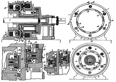
| Abstract:
Planing.-Reversing-gear, for reciprocating machines such as planing-machines, of the type described in Specification 1774/15, has the electro-magnetic clutches arranged to give a positive drive after slip has practically ceased. The friction surfaces D, E, Fig. 2, which are engaged alternately by those on the armature C, are carried by members slidable axially upon, but not rotatable relatively to, the members F, A<2>. Springs d<2>, e<2> maintain the parts in the position shown, as limited by screws d<3>. The magnets are not excited sufficiently to compress the springs until slip has practically ceased, clutch teeth c<1>, c<2> then affording a positive drive. In a modification, shorter additional springs J, Fig. 5, are provided, which give an increased resistance to overcome before engaging the clutch teeth. In a modification, the positive drive may be imparted by a pawl on one part and ratchet on the other, the pawl, normally held clear by a spring, being drawn into operative position by an increase in the magnetic flux. In a further modification, increase in the flux draws a block t<3>, Fig. 8, on to one of the parts, the resulting friction rendering a coil clutch T attached to the other part operative. The clutches may be controlled by a switch having an arm frictionally mounted on the shaft to be reversed and movable between stops. When reversal takes place, the switch arm moves over, cutting a resistance out of circuit with the driving-clutch and inserting resistance into circuit with the idle clutch ready for the next reversal. The frictional mounting of the arm may be controlled by an electromagnet in the main circuit so that, if the control switch is opened to stop the machine, the arm is returned by a centring-spring to a neutral position, thus preventing the machine from being restarted with the switch in such position as to cause engagement of the positive clutches before the parts have come to speed. The planer-table tappets may be arranged to throw over the reversing-switch in two stages, the first stage being arranged to supply current to the clutch magnet through a resistance, and the second stage cutting out the resistance. In further modifications, the resistance is controlled by a centrifugal governor or by the movement of the clutch armature itself. Electromagnetic clutches of the type described may be employed otherwise than in reversing-gearing. Fig. 15 is a diagram of connexions. The switch S operated by the tappets controls the clutch coils f<1>, g<1> and, at the same time, interchanges variable resistances n<3>, n<4> in series with the motor field winding. At the moment of reversal, the switch H moves to a central position, switching the resistance R into the clutch circuit. After reversal is effected, the switch moves over, cutting out the resistance. The main clutch switch Z is such that the circuit first closed always includes the resistance. R, later contact at z<2> serving to render the switch H operative. In a modification, a plain throw-over switch H is employed in connection with two resistances R. |
|