GB Patent: GB-190,601,893
|
| Improvements in Apparatus for Changing the Speeds and or Reversing the Motion of Belt or Rope Driven Mechanism
|
|
Patentee:
|
|
| Joseph Hartley Wicksteed (exact or similar names) - Leeds, England |
| Manufacturer: |
| Not known to have been produced |
|
|
Patent Dates:
|
| Applied: |
Jan. 25, 1906 |
| Granted: |
Jan. 10, 1907 |
Espacenet patent
Report data errors or omissions to steward
Joel Havens
Joseph Hartley Wicksteed
"Vintage Machinery" entry for Joshua Buckton & Co.
|
|
Description: |
| Note: Early English patents (pre 1916) were numbered by the year and started at patent #1 at the start of each year in January. The patent # used in DATAMP represents the year of issue of the application and the patent #. This patent is #1893 of the year 1906.
Abstract:
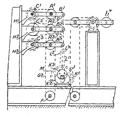
Relates to an arrangement for changing the speed and revers ing the motion of belt, rope, and chain driven mechanism by raising or lowering the pulleys to adjust the tension of the belts &c. In Figs. 1 and 2 are shown a series of pulleys or drums A', A', A<3>, mounted on arms B<1>, B<2>, B<3> pivoted about the shafts C<1> C<2>, C<3> and driven at various speeds through suitably-sized drums by motors H<1>, H<2>, H<6>. Each of the pulleys A' ... is adapted to drive the shaft F through the belts G<1> ... The ends of the arms B<1> ... are supported by rods L<1> ... which are actuated by cranks, cams, or eccentrics K' .. mounted on the shaft J, so that, by rotation of a wheel M, any one belt may be tightened and the remainder slackened to give a particular speed or a reversal. The arms BI ... may be pivoted about the same shaft, or arranged to point towards each other, as shown in Fig. 1<A>, a balance weight b <x> being provided in this case. The eccentric-rods L<1> ... used for raising and lowering the pulleys may be provided with a screwed adjustment l<3>, Fig. 1<c>, and the eccentrics, when used in pairs, may be balanced on either side of the eccentric shaft and, in further modifications, connected by a chain led over suitably - supported pulleys, or by a balance beam. Each pulley arm may also be actuated from the shaft J by a pair of toggle-arms. The mechanism is also described in connexion with a planing-machine. In this application, shown in Fig. 4, the rocking shaft J carries a pinion M<2> actuated by a curved or straight rack M' connected to the starting- handle M by the lever N<1> and rod N<2>. The shaft J is also adapted to be actuated, through the rack M, by some suitably-moving part of the machine the speed and direction of which are to be changed. The motor H<x> on the shaft E drives the pulleys A', A<2> mounted on the pivoted arms B<1>, B<2> through suitable spur gearing, and, in place of the stopped driving-pulley A<2>, a simple pulley with spur gearing as shown in Fig. 4 may be arranged above the driven shaft F. The gearing may also be arranged beneath the table. |
|